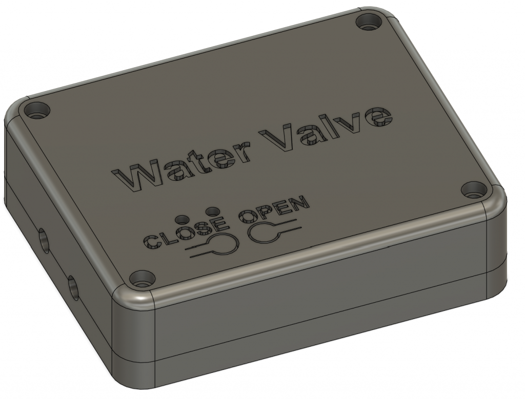
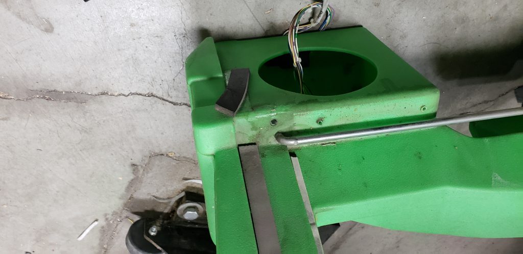
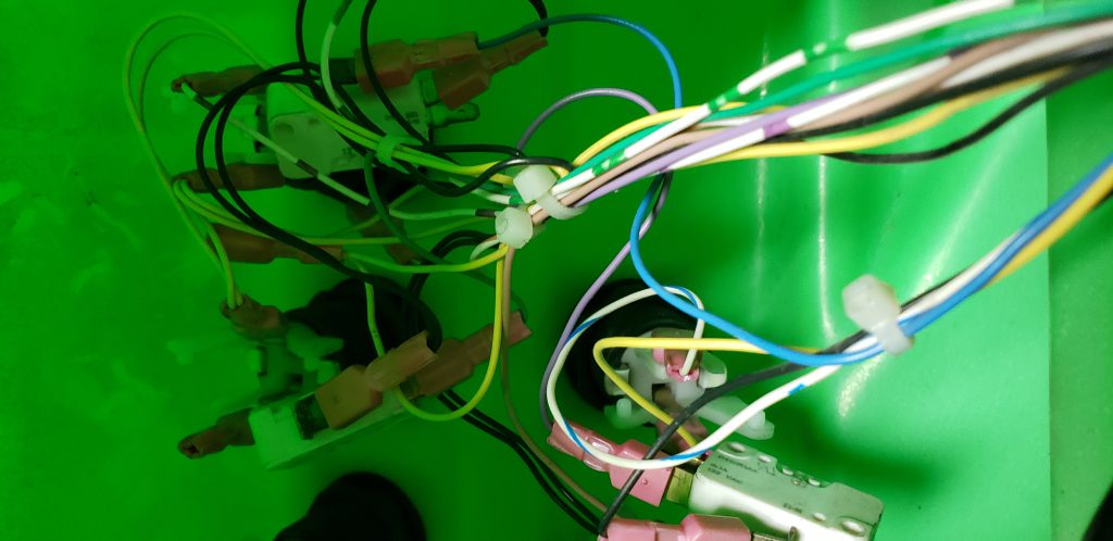
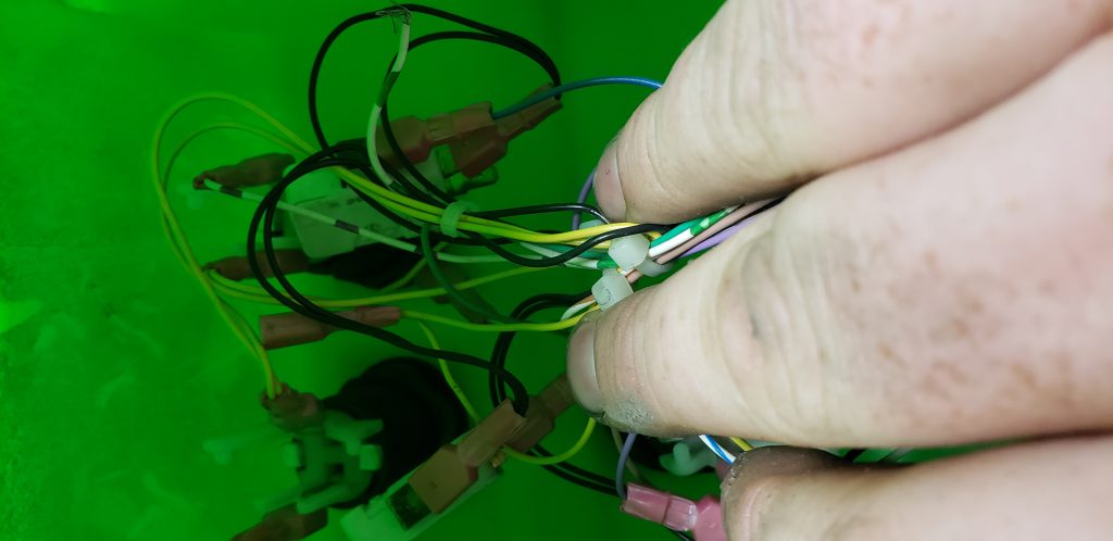
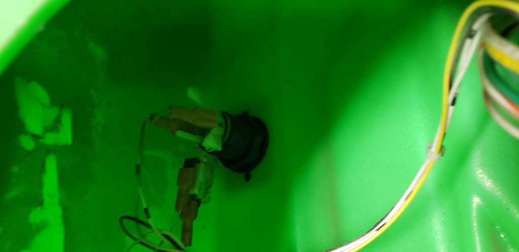
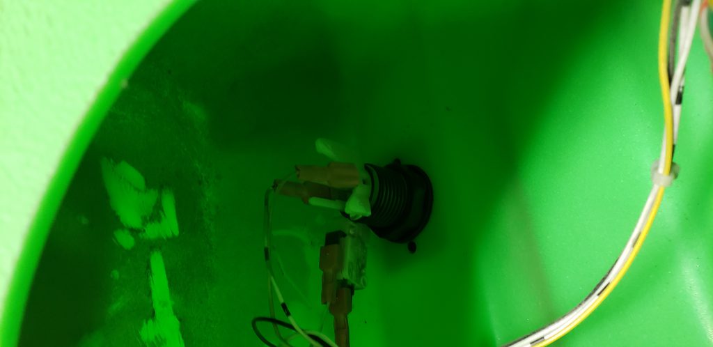
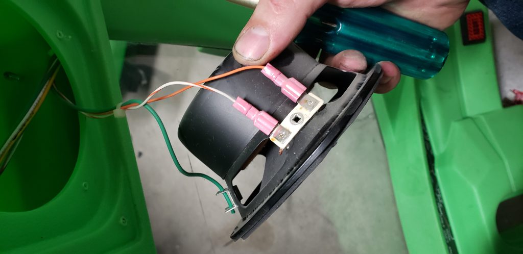
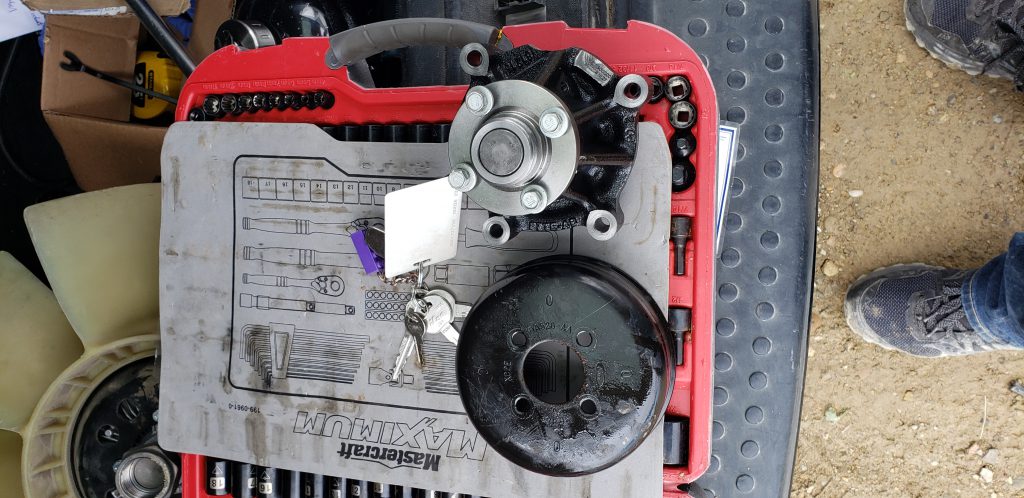
Water Leak Monitoring
Fed up with playing a perpetual game of water whack-a-mole due to pesky leaks in my home, I decided to take matters into my own hands and become the DIY superhero of plumbing mishaps. Armed with determination and a soldering iron, I concocted a water sensing circuit paired with a shutoff valve, dubbing it my "Aqua Avenger" creation. Now, when a leak dares to rear its soggy head, my trusty circuit detects it faster than a cat spotting a laser pointer, swiftly shutting off the water flow and saving the day. Who needs a plumber when you've got a bit of ingenuity and a pinch of humor?
Features
- MQTT control, valve can be open/closed/locked open/locked closed by sending it MQTT messages via a broker.
- MQTT status updates for valve position, sensors missing, button presses, sensor status, and connection issues
- Configurable open/close durations (not all valves close in 10 seconds)
- Easy Wifi setup, unit powers up in a wifi station mode with a randomly generated password for each device, this password is output via serial when the device is first powered on and printed on a sticker on each device.
- Dynamic or static IP configuration, once again setup during the initial process, or can be modified from the web UI
- Stored log events, the device stores a log of the last 20 events in memory along with their timestamps, this includes, errors, warnings and status updates for valve operations.
- Manual and web-based valve control, buttons on the physical device, manual pin for controlling without power as well as web based and MQTT control for controlling the device remotely.
- Ability to lock the valve even if sensors are triggering. Once a problem has been resolved the water sensors can take time to dry out. The web interface provides controls for locking a valve in an open state regardless of sensor values
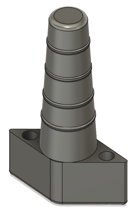
- Support for multiple valves on one network, currently an unlimited number of valves are supported with 25 water sensors per valve, each sensor module can support up to 10 sensor channels, each channel can have a maximum of 18 feet of water sensing wire.
- Web-based firmware updater for both the valves as well as the sensors. Valves have the ability to push firmware automatically to each sensor during the registration process.
- Supports user/password login with token-based authentication. Unfortunately still using HTTP, HTTPs is not supported at this time.
- Sensor whitelists to provide notifications when sensors are missing for more then a configurable number of seconds
- Single web interface that allows access to all individual sensors and their settings using token-based authentication between devices
Needed an Air Mattress Plug
I couldn't find them to buy locally so I decided to print this in TPU. The usual websites didn't have any files available so i quickly created this one. The more infill you use the more solid it becomes.
Problems With Power Pet Dog Door
The Original Problem
In the first few days of dog ownership it was clear to me that letting the dog in and out every time she had to pee was going to be something I would need to do tens of thousands of times over her life… Some quick research lead me to power pet doors which sell a wifi dog door. https://www.hitecpet.com/petdoors.html#petdoors-wifi
This simple door has local controls on the door for open/close/in/out/etc that all work perfect. The dog wears a transmitter on her collar the transmits an ultrasonic tone that the door listens for using 2 sensors, one on the outside and one on the inside. Using these sensors the door can be configured for in-only or out-only operation.
But the coolest feature is that this door has bluetooth and wifi and can be controlled from millions of miles away using an app for IOS and Android. This is where the problems with this product lie. The Wifi control often doesn't work, and takes to long to connect when it does work. It infact takes so long that hitting the door open button in the app usually results in my dog giving up on waiting and just peeing on the floor.
I tried many things with the same horrible results, i tried the IOS app, the Android app, the web interface. All interfaces would only respond to open commands about half the time and often when it shows a connection to the door it is not actually connected. Logging out of the app and logging in again would fix the problem every 3rd attempt or so.
I have now owned the door for 1 year, the problem has been consistant over that entire 1 year span.
The Hardware
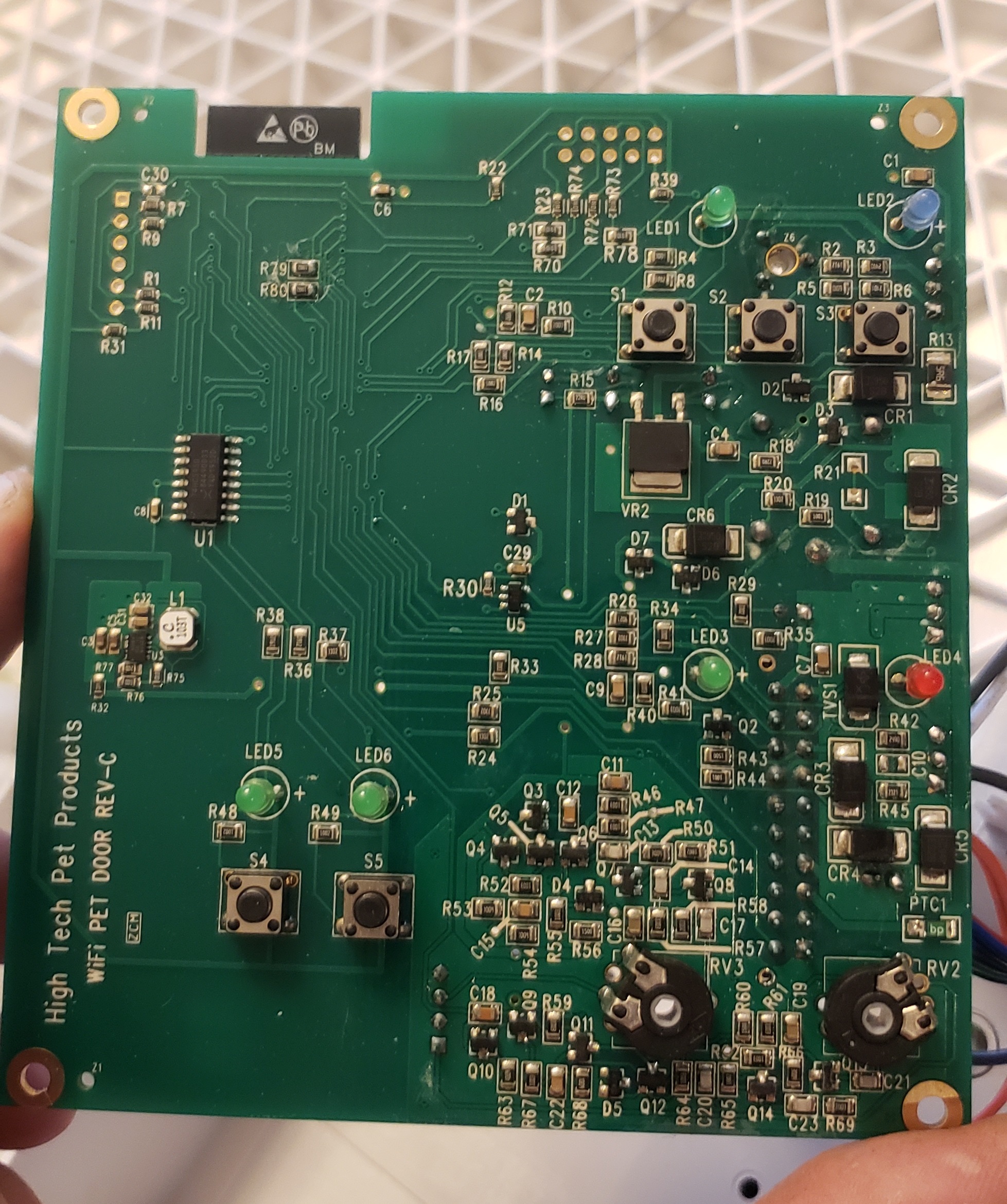
It was obvious that something was wrong with the door… With this problem being so obvious and annoying I have to assume that the problem was on my side. I take the door apart and find that the dog door houses an ESP32 WROOM chip, and some simple circuits to detect the ultrasonic tones, door switches and a simple motor controller circuit for the motor that raises the door. There is even a nice programming header for reprograming the ESP processor. So if all else fails i could write my own firmware to fix this issue if it turns out to be a problem with the vendor.
I find the IP using my routers DHCP table and get a constant ping going to see if maybe Wi-Fi is dropping, causing the door to go unresponsive. After hours of testing I find that the Wi-Fi signal is rock solid, without any dropouts.
Figuring out how this thing works
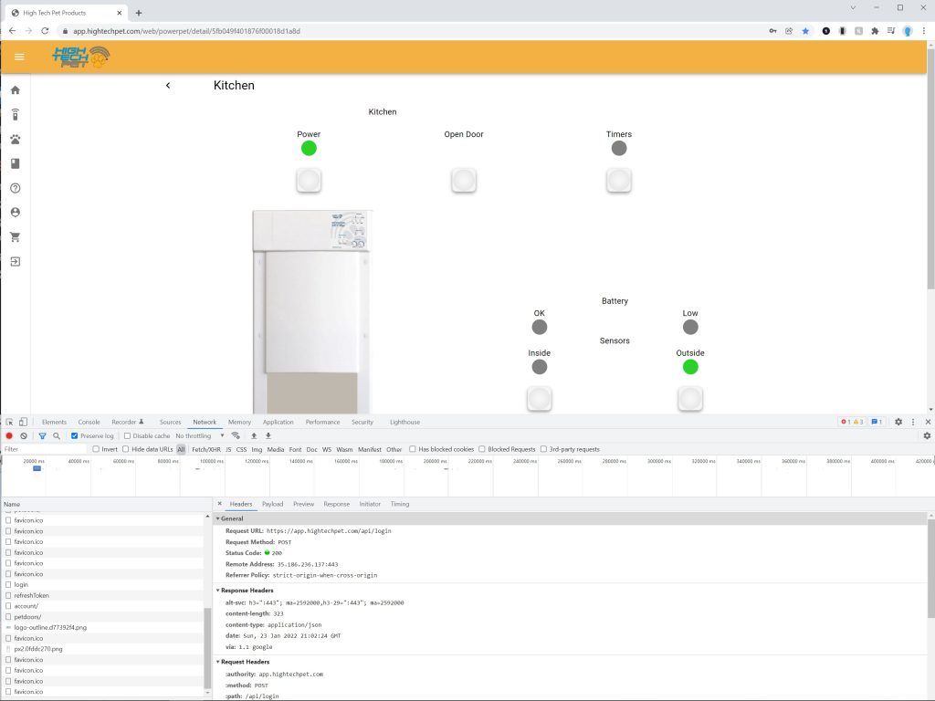
Its obvious at this point that the problem is likely in the products firmware or server configuration/code, I will now need to know how the protocols works before we can drill in a little deeper. The TCP Protocol is a good place to start, one option would be to man in the middle the door using a wireless network in my control, but that would take some time to setup and would require some hardware, so instead I try my hand at reverse engineering the web interface at https://app.hightechpet.com/web/. Using Chrome I open the inspect tools, head over to the "network" tab and start logging in.
The login process is pretty straight forward,
- HTTP Post to https://app.hightechpet.com/api/login with Email/Password and an empty BearerToken results in a JSON Response with a RefreshToken
- HTTP GET to https://app.hightechpet.com/api/refreshToken with our RefreshToken gives us a BearerToken
- HTTP GET to https://app.hightechpet.com/api/petdoors/ with our BearerToken gets us our door details in JSON
There are 2 pieces of information in there that we care about, our ID and the ChannelKey. These are used to connect to an MQTT server that is wrapped beind a Secure Web Sockets (WSS). The MQTT username is "Support" and the MQTT server is "iot.hightechpet.com"
Creating my own Python app
With all of this new information I was able to create a python script that uses the API to grab the ID and ChannelKey and connect to the WSS server. I could then open up the Android app and get a list of all of the commands
Download HERE
- {"config":"POWER_ON","msgId":4201,"dir":"p2d"}
- {"config":"POWER_OFF","msgId":4202,"dir":"p2d"}
- {"config":"DISABLE_TIMERS","msgId":4203,"dir":"p2d"}
- {"config":"ENABLE_TIMERS","msgId":4204,"dir":"p2d"}
- {"config":"DISABLE_INSIDE","msgId":4205,"dir":"p2d"}
- {"config":"ENABLE_INSIDE","msgId":4206,"dir":"p2d"}
- {"config":"DISABLE_OUTSIDE","msgId":4207,"dir":"p2d"}
- {"config":"ENABLE_OUTSID","msgId":4208,"dir":"p2d"}
- {"config":"GET_DOOR_STATUS","msgId":4209,"dir":"p2d"}
- {"config":"GET_HW_INFO","msgId":4210,"dir":"p2d"}
- {"config":"GET_POWER","msgId":4211,"dir":"p2d"}
- {"config":"GET_SENSORS","msgId":4211,"dir":"p2d"}
- {"config":"GET_DOOR_BATTERY","msgId":4212,"dir":"p2d"}
- {"config":"CHECK_RESET_REASON","msgId":4213,"dir":"p2d"}
- {"config":"GET_SCHEDULE_LIST","msgId":4214,"dir":"p2d"}
- {"config":"GET_SETTINGS","msgId":4214,"dir":"p2d"}
- {"config":"HAS_REMOTE_ID","msgId":4215,"dir":"p2d"}
- {"config":"HAS_REMOTE_KEY","msgId":4215,"dir":"p2d"}
- {"config":"GET_DOOR_BATTERY","msgId":4216,"dir":"p2d"}
- {"cmd":"OPEN_AND_HOLD","msgId":4217,"dir":"p2d"}
- {"cmd":"CLOSE","msgId":4217,"dir":"p2d"}
- {"cmd":"OPEN","msgId":4218,"dir":"p2d"}
- {"PING":"9082340589","dir":"p2d"}
Door Events (Door transmits these)
- {"success":"true","dir":"d2p","CMD":"OPEN"}
- {"dir":"d2p","CMD":"DOOR_STATUS","success":"true","delta":0,"door_status":"DOOR_RISING"}
- {"dir":"d2p","CMD":"DOOR_STATUS","success":"true","delta":960,"door_status":"DOOR_SLOWING"}
- {"dir":"d2p","CMD":"DOOR_STATUS","success":"true","delta":1630,"door_status":"DOOR_HOLDING"}
- {"dir":"d2p","CMD":"DOOR_STATUS","success":"true","delta":1630,"door_status":"DOOR_CLOSING"}
- {"dir":"d2p","CMD":"DOOR_STATUS","success":"true","delta":1870,"door_status":"DOOR_CLOSING_TOP_OPEN"}
- {"dir":"d2p","CMD":"DOOR_STATUS","success":"true","delta":3380,"door_status":"DOOR_CLOSING_MID_OPEN"}
- {"dir":"d2p","CMD":"DOOR_STATUS","success":"true","delta":4440,"door_status":"DOOR_CLOSED"}
- {"dir":"d2p","CMD":"DOOR_STATUS","success":"true","delta":4440,"door_status":"DOOR_IDLE"}
Protocol is pretty easy to to figure out, "dir" is "p2d" for commands sent to the door and "d2p" for commands coming from the door.
It was at this point that I learned a few more details
- The server disconnects automatically after exactly 10 minutes, doesn't matter if you send pings or not
- The Door often disappears from the server for a period of exactly 10 minutes at a time
- Events from the app sometimes appear and sometimes do not appear, this problem comes and goes in 10 minute shots
- disconnecting and reconnecting my app multiple times (<3 usually) will eventually result in responses from the door.
So the problems i was seeing with the IOS and Android app are impacting my app as well. But why are all the weird results in 10 minute durations, this has to be a clue.
Getting to the bottom of the problem.
It's at this point that I had a theory, I think there are multiple MQTT servers behind a load balancer and 1 or more of those servers are not relaying information back to the other servers. I do a quick DNS resolution on the WSS servers but this is a dead end, the servers are not using DNS based load balancing.
I open up 10 instances of my python app, each one connects to the same DNS entry, each command issued shows up in about half of the other windows, if I move to the other half of the windows and issue a command, that command gets repeated in those windows but not the other half. BINGO!!!!
So there are 2 MQTT servers or clusters that the load balancer is handing out but they do not transmit messages between them. If I open the Android app or connect to the web interface I can see that randomly they connect to one of the two servers and issue a series of commands, the app always shows as connected even when connected to an MQTT server that does not have the door connected. Pressing on any buttons in those interfaces results in no action.
So now we know the problem, how do we fix it
- Let the company know, maybe they will fix their backend
- Rewrite my app to constantly (every second) query one option on the door, when no response, disconnect and reconnect, issue the command again, repeat until the door responds, stay connected until the door goes unresponsive again. This will work but may leave sections of time where the door is unresponsive for 10 seconds or more and it will hammer their server.
- Create my own WSS server, sign it with my own internal certificate and spoof the DNS for the real server on my internal network. This assumes the ESP does not validate that the cert is valid. (this is likely to work) This also has the added benefit of removing the cloud from my cloud hosted door.
- Write my own firmware for the ESP to connect to my MQTT server and ditch the cloud service.
Why me, why are not all customers complaining about this?
This is a server problem, how are more users not having this problem.
If I ping the server and then do a reverse lookup on its IP i get the real server name of 116.251.186.35.bc.googleusercontent.com. This server could very well be specific to my region of Canada. Its also now clear that Google is hosting the infrastructure for this service via Google Cloud Provider, my bet is that its using this offering https://cloud.google.com/iot-core.
C:\Users\user>ping iot.hightechpet.com
Pinging iot.hightechpet.com [35.186.251.116] with 32 bytes of data:C:\Users\user>ping -a 35.186.251.116
Pinging 116.251.186.35.bc.googleusercontent.com [35.186.251.116] with 32 bytes of data:
In Conclusion
I will send an email off to the manufacturer linking back to this article and see what traction I can get on that side. At least I know what's wrong now.
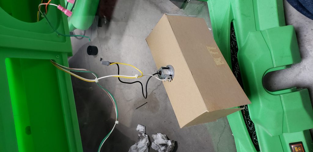
Auto Filling Dog Bowl
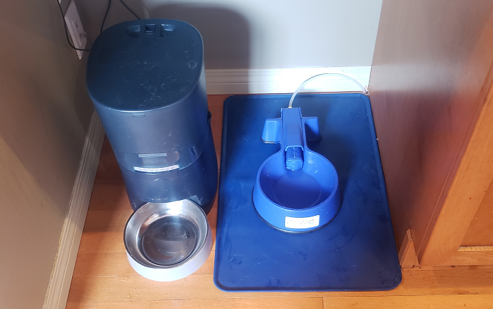
A few months back we adopted a dog from AARCS animal rescue. To lessen some of the daily routine I invested in an automatic dog food dispenser. I was looking for a similar solution to ration out water and this is what i came up with.
Parts
- Easy clean water bowl: https://www.amazon.ca/gp/product/B00RAQBH54/ref=ppx_yo_dt_b_asin_title_o00_s00?ie=UTF8&psc=1
- 12 Volt Timer https://www.amazon.ca/gp/product/B01MRWKVM0/ref=ppx_yo_dt_b_asin_title_o00_s01?ie=UTF8&psc=1
- Solenoid https://www.amazon.ca/gp/product/B01GL5P304/ref=ppx_yo_dt_b_asin_title_o00_s02?ie=UTF8&psc=1
- Sharkbite Connector to T into basement water line https://www.amazon.ca/gp/product/B016M169KU/ref=ppx_yo_dt_b_asin_title_o00_s01?ie=UTF8&psc=1
- Fittings to convert Solenoid to 1/4" https://www.amazon.ca/gp/product/B0773P7Z9Q/ref=ppx_yo_dt_b_asin_title_o04_s00?ie=UTF8&psc=1
- Fittings to convert Solenoid NPT to 1/4 OD https://www.amazon.ca/gp/product/B07XDWCDYM/ref=ppx_yo_dt_b_asin_title_o03_s00?ie=UTF8&psc=1
- Braded line upgrade (optional, I did not do this at first) https://www.amazon.ca/gp/product/B08QPTZWBW/ref=ppx_yo_dt_b_asin_title_o01_s00?ie=UTF8&psc=1
- 12 Volt power supply https://www.amazon.ca/BENSN-Compatible-Universal-Household-Electronics/dp/B082XRJ4LN/ref=sxin_9_ac_d_rm?ac_md=1-1-MTJ2IHBvd2VyIHN1cHBseQ%3D%3D-ac_d_rm&cv_ct_cx=12+volt+power+supply&dchild=1&keywords=12+volt+power+supply&pd_rd_i=B082XRJ4LN&pd_rd_r=a337a1a3-5456-48af-94b4-f6e8866fb0a3&pd_rd_w=Oh4U0&pd_rd_wg=ckefC&pf_rd_p=8642c3cb-9fcf-4c84-93d6-c72c3fa128ad&pf_rd_r=1WD2GHA7A46RS923QXVB&psc=1&qid=1614293201&sr=1-2-12d4272d-8adb-4121-8624-135149aa9081
These parts together will create a water bowl that you can schedule fill times on. Currently I have programed the bowl to fill at 7AM and then top up again at 9Am, 11Am, 1Pm, 3Pm, 5Pm. Each time the water fills for a period of 1 minute and then stops. The float inside the dish will stop the dish from overfilling.
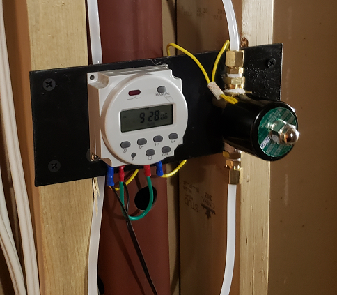
This is what the timer and solenoid look like in the basement, I mounted everything to a metal plate and secured it to the wall beside my furnace.
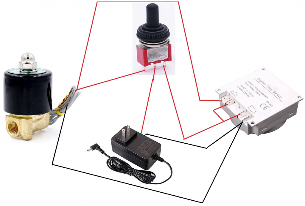
If your interested in recreating this, here's the basic wiring diagram that also adds a 3 position override switch that allows the system to be bypassed on, bypassed off, or set to auto
My Atari 7800 Needs an RGB mod.
Over the last few weeks of Covid isolation i have been working to RGB mod each and every console i own that came out before the invention of component or HDMI. Every console has a published solution or kit that i was able to purchase/build and install with the exception of one console. The Atari 7800.
Most consoles have a native RGB signal on the board that just needs some simple tweaks to bring it in compliance. Those that do not require more work, solutions vary from adapting existing signals, assuming they are of sufficient quality, up to the much more difficult complete emulation of the graphics chip.
The Atari 7800 problem goes one step further. There is no signal on the motherboard that holds sufficient quality to adapt. On top of that the 7800 has two graphics processors, the Maria chip, for 7800 games and a 2600 chip called the TIA to run the older 2600 games.
Now to finding a solution.

There is already a solution for RGB modding the 2800 by desoldering the TIA chip on the 2800 and adding a board that intercepts the signals on route to the the TIA chip http://etim.net.au/2600rgb/ , it uses at 64 GIPO processor (the cy8c3244axi) to read the address lines in real time and recreate the video output using a tr9c1719-66dca video DAC with 3 channels (red, green, blue). i own one of these boards and it works great.
The solution for the 7800 requires solving 2 problems, the first is to render the data destined for the Maria chip (for 7800 games) and to render data that was destined for the TIA chip (for 2600 games). My focus here is to make this work for 7800 games first, the 2600 problem already has s solution, once the 7800 works 2600 support can be added in later
Option 1, drop in replacement for Maria. Someone has already done the leg work to reproduce the chip https://atariage.com/forums/topic/154745-maria-chip-has-been-resythensized/page/5/#comments this could be adapted to add RGB functionality. But silicon is expensive.
Option 2, unsolder the Maria chip, install a header and use a small board to tap into the address lines, data lines and chip enable lines. The address bus under the maria chip is the same used by the TIA chip so these same pins could read data destined for the 2600, we just need to monitor a different address space. We may need an additional wire to the TIA enable pin however i think we can assume if the Maria enable pin is low the TIA enable will be high (easy to test)
So lets start down the path of option 2 and see if we run into any problems. First we will need the pinout of the Maria chip

| A0-A15 | memory address bus |
| D0-D7 | memory data bus |
| Vss | ground |
| Vdd | power |
| /NMI | output to cpu |
| XTAL1 | 14 MHz input |
| XTAL2 | main clock output |
| MEN | Maria enable input. When lo, video is off and memory map is 2600 |
| Ø2 | phase 2 clock input |
| TCLK | TIA main/4 clock |
| Ø0 | phase 0 clock output. 1.79M or 1.19M |
| DEL | delay line control voltage input |
| /SRAM0-1 | RAM chipselects |
| /SEL32RIOT | chipselect |
| /TIASEL | TIA chipselect |
| R/W | Read/write input |
| /HALT | cpu halt output |
| READY | cpu ready output |
| LUM0-3 | luminance output |
| COLOR | color output |
| BLANK | blank output |
| SYNC | video sync output |
There are 4 versions of this chip
C024674 7800 NTSC older
C025349 7800 NTSC newer
C025314
C025718 7800 PAL
I believe all 4 have the same pinout. It looks like this pinout will give us all the signals we need plus a few we dont. The plan will be to use this chip still, we are just going to watch signals move between the bus and the chip and recreate a video output, existing composite/rf/svideo mods will not be impacted. The address bus also has the TIA chip as well so we will see traffic destined for the 2600 chip as well, Maria will be ignoring it but we dont have to.
Now that we know the basic hardware layout we need to know the address space the maria chip works with and what each address in that space would normally do. I was able to find this site that lays out the addresses of each chip https://atarihq.com/danb/files/78map.txt as well as the addresses used inside the Maria chip.
Then i found this fantastic document http://www.atari7800.org/manuals/7800_Maria_Specs.pdf that outlines the behavior of the Maria chip, descriptions of the physical chip, etc.
I also found this great diagram that shows the timing cycles that the Atari uses. Turns out the resolution output of the Atari is not set in stone, Program code has to run in the blanking period however if your game did not need as much time for processing its possible to shorten the blanking period and increase the horizontal or vertical resolution.

The next step for this project is to:
- Remove the Maria chip from my console
- Add a socket
- Have a board made that breaks out all maria pins to an IDE cable header
- Make another board that brings the IDE cable header into a breadboard.
- Decide on a suitable processor that is fast enough to build and put one frame worth of data into a tr9c1719-66dc before the next frame needs to be built. I think i will only need one interrupt triggering off the clock signal. I bet i could use the same processor currently used by the Atari 2600 RGB mod.
- Write code to interpret the data and output 7800 frames to my computer over a debugging cable. (doesn't have to be real time at first)
- Optimize that code to run fast enough to not lose any frames
- Write code to output those frames to the tr9c1719-66dc instead of my computer
- Breadboard up the tr9c1719-66dc along without outputs to scart using a BH7236AF, test
- Draw up the final circuit in easyeda, get some boards made
- If everything works shift focus to write software that attempts to render 2600 video using the same address pins and maria enable pin.
Extra considerations
- The palette will need to be recreated (color reproduction on Maria would be approximate, colors are set into the palette addresses on the Maria chip, we get to interpret those colors how we see fit. The NesRGB handles this buy having several options selected with a switch, we could do the same. People always have opinions about this kind of thing (we could get the color RGB values from framemeister configs meant for the Atari 2600)
- i could cheat and buy a https://etim.net.au/shop/shop.php?crn=210&rn=552&action=show_detail 2600RGB, simply make an adapter board that moved the address pins from the TIA layout to the Maria layout, I would need to add a few additional address lines because the TIA has a smaller address space, maybe i could borrow them from other pins or add a few bodge wires. I could then erase the data on the 2600RGB and replace it with my 7800 firmware. This could speed up prototyping
- I should look into how controller input is read, maybe that comes across the address bus, if i could capture input i could use controller combinations to set pallet information (up up down down left....). Or maybe i could read the consoles physical switches. **UPDATE** Controllers are read directly into the 6532 RIOT chip, this data does go across the bus, to the CPU, i can sniff this data as goes across the bus.
- While a simple board gets us 2600 and 7800 video signals, we still need additional wires to get audio (its not part of the Maria chip). Audio comes from the TIA chip as well as the cartridge slot. I need to grab this signal after they are mixed together, maybe at the RF modulator, voltage levels will need to be checked. This should also run through a small non polarized capacitor before being sent out the scart cable.
Sources
- http://www.atari7800.org/manuals/Devcard.htm
- http://www.atari7800.org/manuals/7800_Maria_Specs.pdf
- https://atarihq.com/danb/files/78map.txt
- https://atarihq.com/danb/a7800.shtml
- https://atariage.com/forums/topic/244830-maria-diagram/
- https://atariage.com/forums/topic/154745-maria-chip-has-been-resythensized/#comments
- http://www.qotile.net/minidig/docs/stella.pdf
- https://atariage.com/7800/archives/schematics_ntsc/
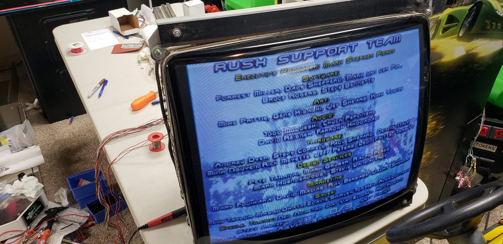
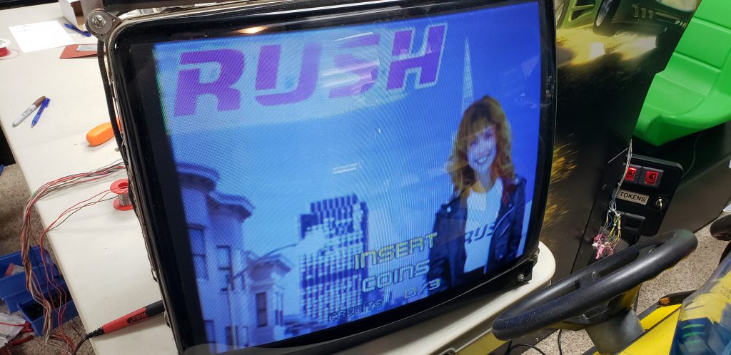
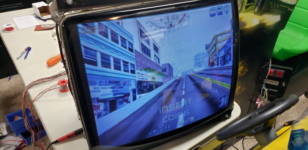
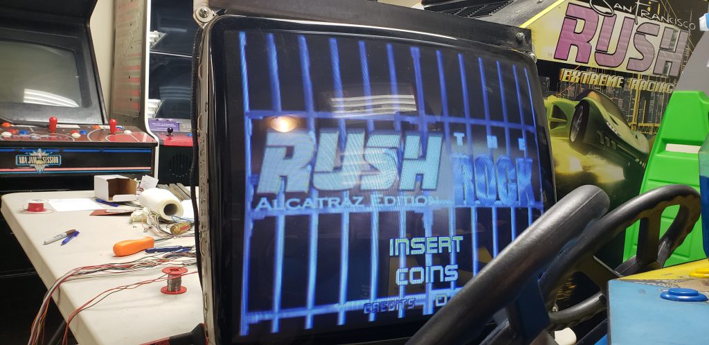
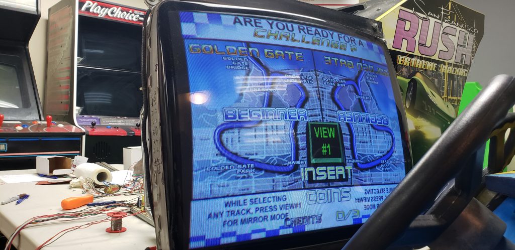
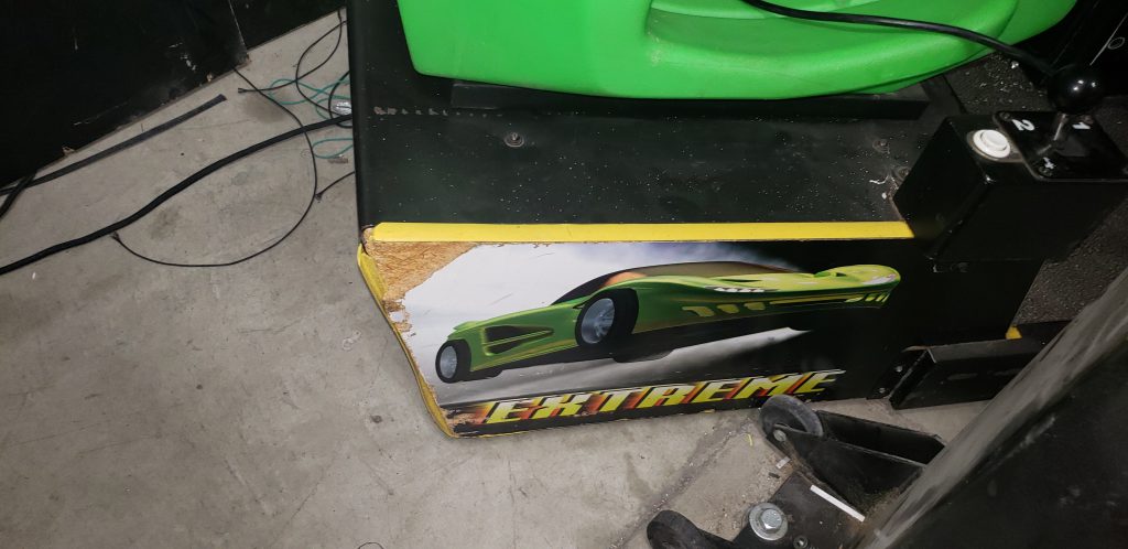
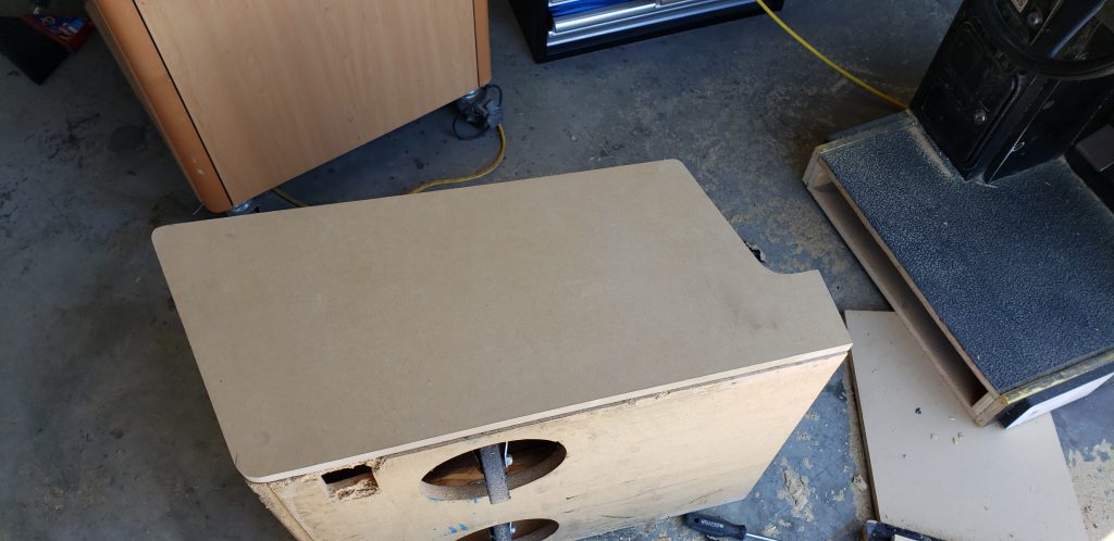
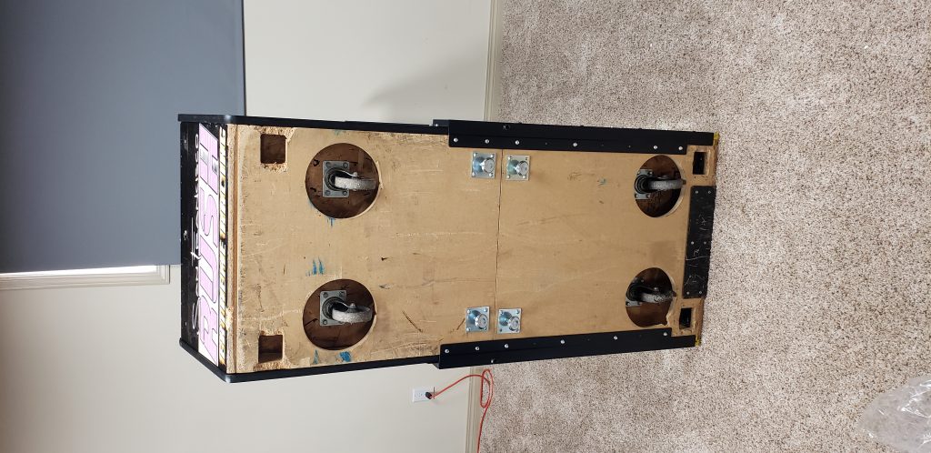
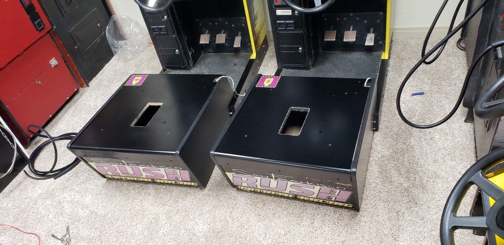
I now have a pair of San Francisco Rush cabinets.
There are a few items that I like to search for on Kiiji every day waiting for the right deal to come around. One of those is a linked set of arcade racing games. I wanted something with force feedback wheels and 3D graphics.
On a search last week I found a pair of units for $700 that needed a little TLC in Edmonton, one city away from me. I send the current owner an email letting him know that I would buy them sight unseen for $700 and sent him over a down payment of $200 to show him I was serious.
I took the next day off work and a friend and I drove down to Edmonton to pick them up.
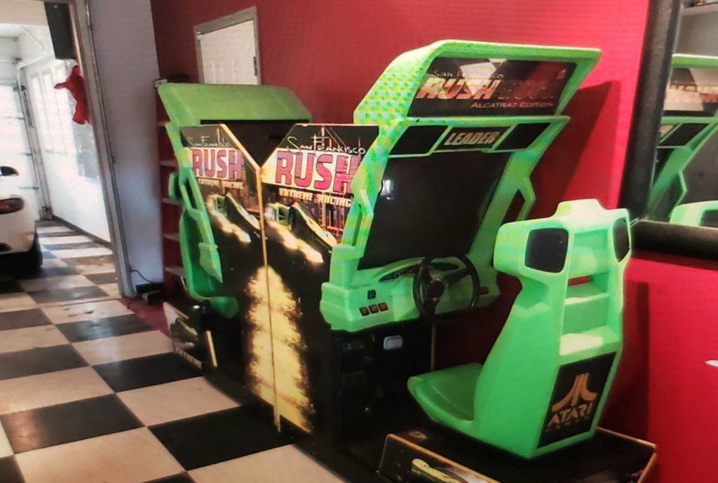
The units were in fairly good shape but they have a few issues.
- The previous owner did not have the keys so I had to drill out all the locks
- One wheel has no force feedback and won't calibrate
- One wheel only has force feedback in one direction
- Both monitors are oversized horizontally and the monitor controls cannot resize the image
- One monitor is VERY dark
- One HDD works sometimes fails sometimes
- One topper has a light that doesn't work and crack in the marquee
- The seat units are not removable (needs modification to fit into my basement)
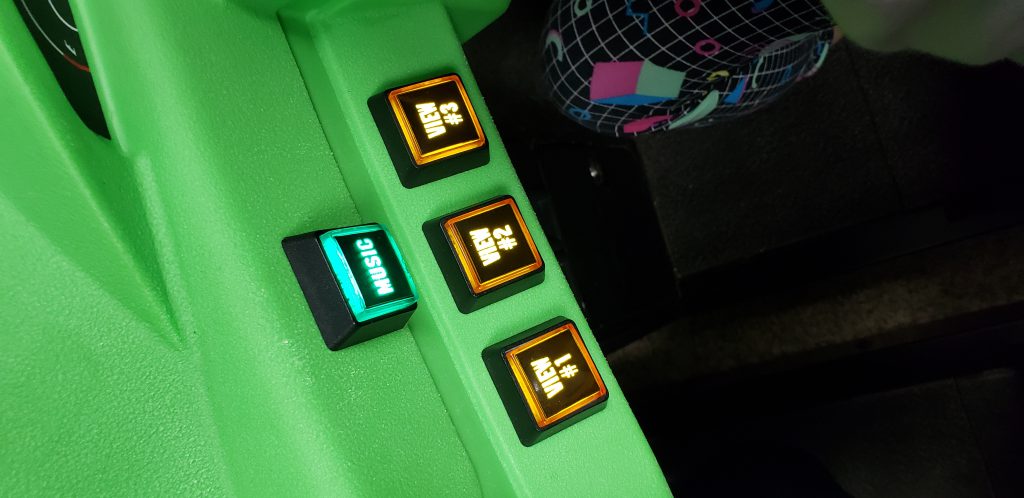
- The lights on many of the buttons do not work, the wires have been ripped off.
- The view 2 button on one unit does not work
- The batteries that save high scores are both dead.
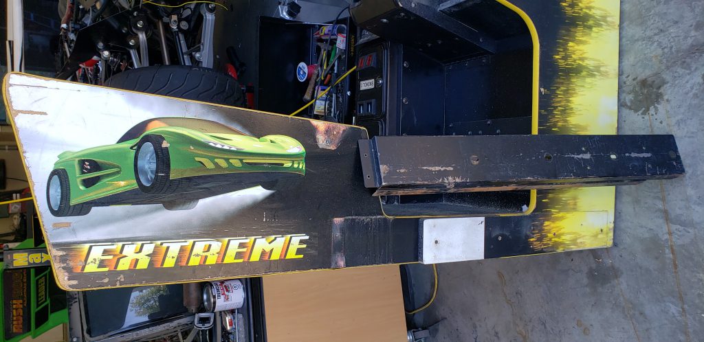
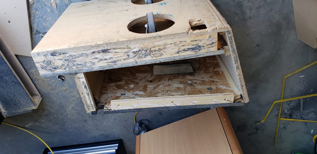
- The wood around the seats is damaged on both units.
- The wood that covers the back is damaged on both units
- The seat sliders are very loose
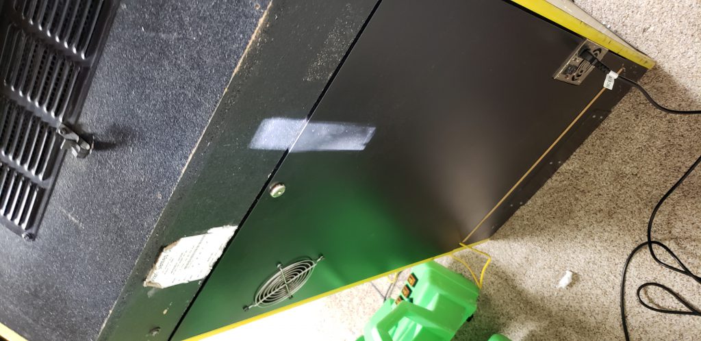
- The unit is VERY Dirty... and Very hard to clean
While that is a long list, its nothing that can't be fixed.
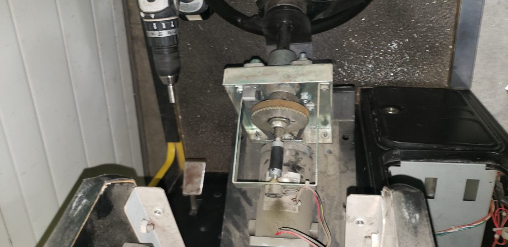
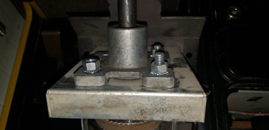
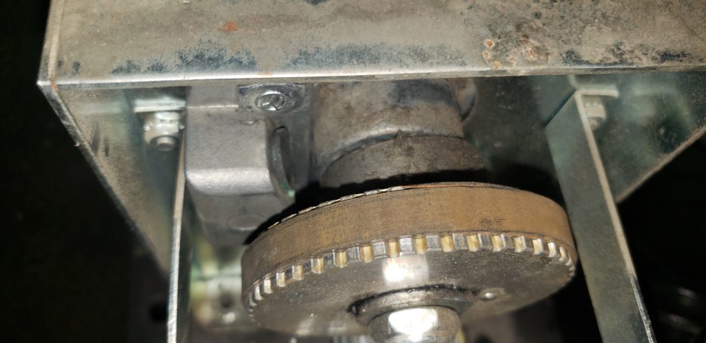
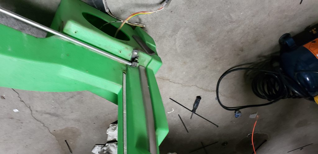
I got the units home and started tearing into the steering and force feedback problems so I could play a game with my kids. Starting with the first unit i removed the 4 security Torx screws that hold the wheel in place. Once the metal plate was free 4 bolts fell out along with a metal bracket. They must have backed there way out over the years. The motors belt had fallen off as a result. The metal bracket that came loose is the bracket that stops the wheel from turning to far in one direction.
Great, this should be an easy fix. All I needed to do was put the bolts back into the right place and reset the wheel potentiometer once the wheel was centered. (Turned out this was just one of a few problems with the wheel)
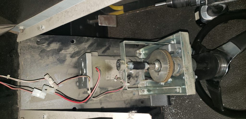
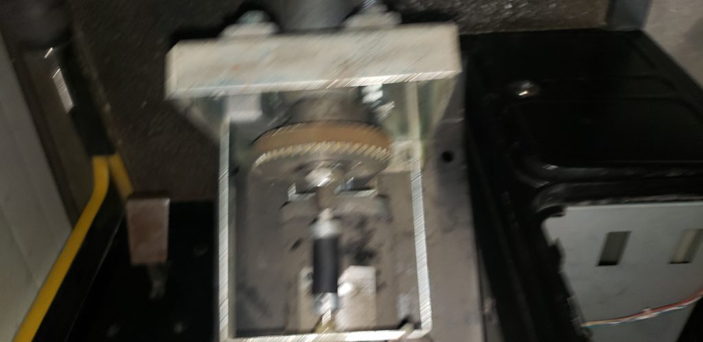
One wheel down. Onto the other unit. The force feedback system only works a little. It seems like the force feedback system will only turn the wheel to the right, not to the left. I started off by removing the logic board that controls the motor. I then put that board into the machine i had fixed previously. The previously working unit now had the same problem as the non-working unit. Crap! I now know the board is faulty and these boards are not cheap.
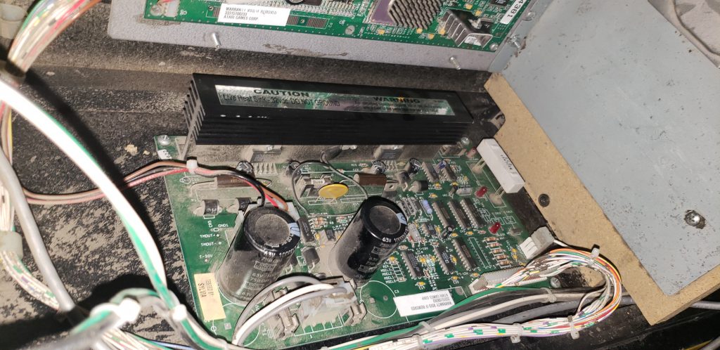
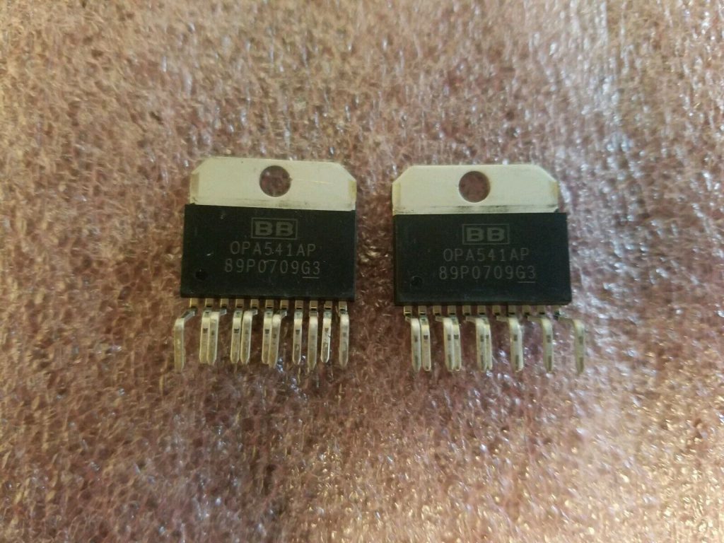
At the top of the image above you can see that the force feedback control board uses two OPA541AP Operational Amplifier chips that are attached to the large heat-sync. It seems that these chips are a common failure point (thanks google). I ordered 2 new chips off of ebay for $46 USD. The existing chips needed to be removed using a desoldering iron and then the new chips installed. Truthfully one chip would have fixed the problem however I didn't know which chip was bad and 2 chips is cheap insurance that this problem wont happen again. After soldering in both chips the steering worked great for about 2 minutes. Then I hear a pop followed by the smell of burnt electronics. Turns out the OPA chip being blown was only a symptom and not the cause of the problem. I ordered a new chip, found the bad components on the board, replaced everything and tested again. Success!
Now I have two functioning units and was able to play the game with my kids for an hour or two. The next problem that was getting in the way is that one monitor is Very dim. I was able to make the monitor better by adjusting the brightness on the flyback. But this leaves the image all washed out.
At this point its time to buy some parts.
- 2x Monitor Cap Kits $20USD
- 2x Monitor Flybacks $60USD
- 2x Monitor Hot Chips $10USD
- 2x Monitor Pincushion cap kit $10USD
- 6x key lock tumblers $26USD
- 8x Metal plates with leg levers to use when cutting apart the cabinet. $26USD
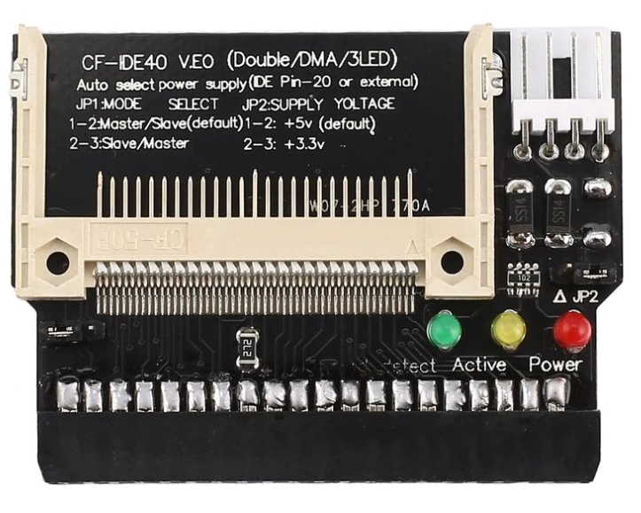
- 2x 4GB compact flashcards (to replace the HDD's) $15.57USD
- 2x Compact flash to IDE adapters (to replace the HDD's) $5.32USD
- 2x 3.5" power to floppy drive power $1.84USD
- a new marquee $29USD
Total $203.73 + the chips i bought previously brings the parts total to $249.73
To order those parts i also had some additional costs
- $50 USD for shipping
- $10 CAD from Canada Post to create a Money Order
- $27 CAD to ship the Money Order
- $20 CAD for the vendor to cash the Money Order (they dont take credit cards or bank transfers from Canadians)
Now my total for parts is $93.19 USD + $249.73 = $342.92 USD or $452.57 CAD. This brings the project total for 2 completely working units to $1152.57 CAD (still a pretty good deal)

New parts in hand there are a few more problems that need to be tackled. I started with an easy one. Saved highscores and settings were not been stored after the unit was unplugged.

I bought a set of 4x 2032 batteries, popped one in each unit in the middle of the mainboard. Problem solved. Onto the next issue!
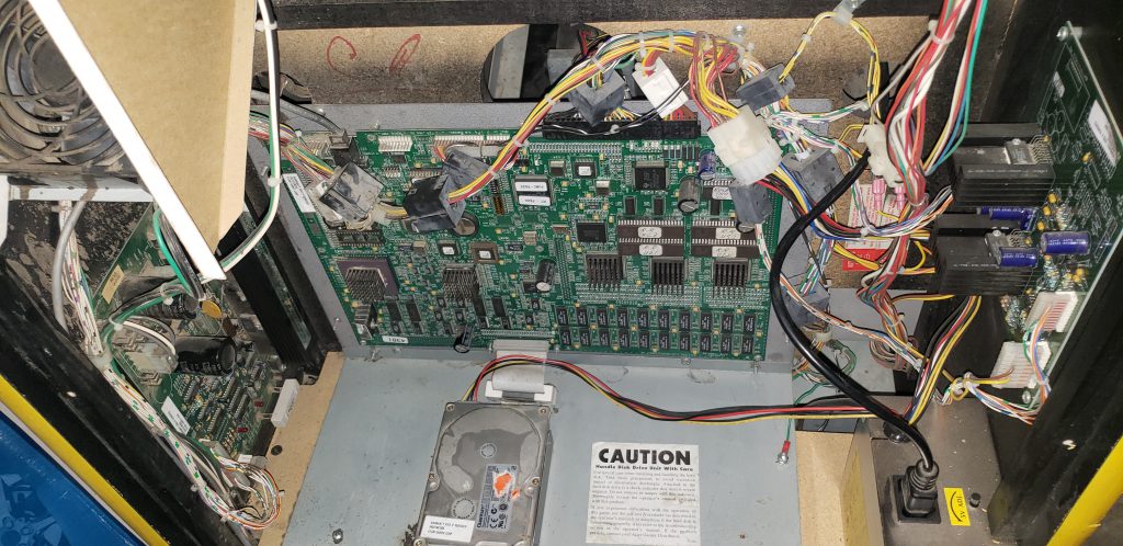
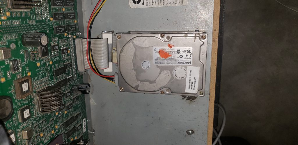
Fixing the HDD is up next. Each unit has an old style 4GB IDE drive that stores all the game images and level data. These hard drives are from 1994 according to the warranty sticker and are failing. the fix is simple. Remove the old hard drive, use an IDE to USB adapter to image the drive using the Mame tool chdman to my home computer. Then use the same IDE to USB adapter this time hooked to a solid-state compact flash chip in an adapter. The game will have no idea that the new compact flash chip is different then the old spinning disk. The chdman tool is used again to image the compact flash drive from my local pc. I also saved these files to a DVD and placed them inside the unit in case they are needed in the future.
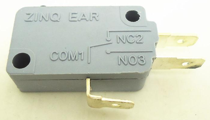
Looking to knock off some more easy problems I replaced the small micro switch on the View 2 button, now it works. The lights inside the buttons were fixed by putting new connectors on the wires that go to each bulb and replacing every light bulb with the appropriatly colored LED.
The Marquee light had 2 problems and was fixed by removing the cover and putting the bulb back into its socket and replacing the bulb starter. Maybe the bulb came out when we were hauling it back to Calgary. At the same time, the new marquee is easily added back during assembly. At this point i tried to clean both marquees and broke the other old one (it was very brittle. So I bought one more new marquee.
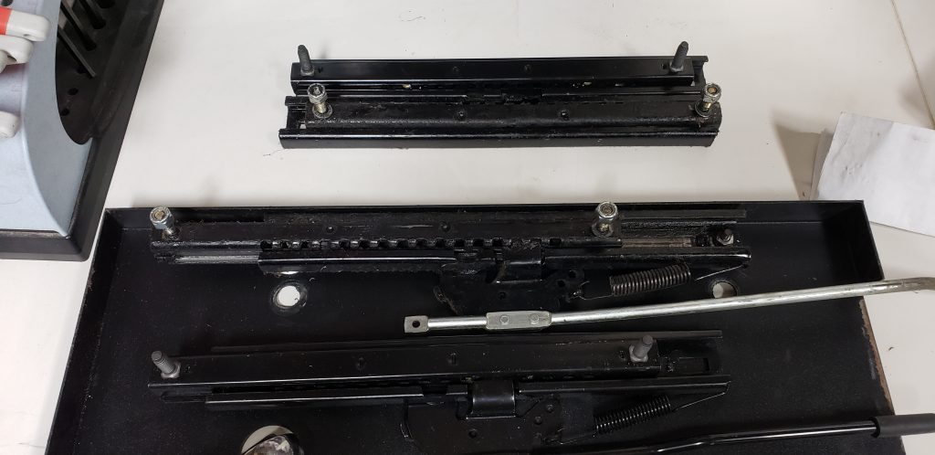
Each lock was easily removed by drilling the lock with a 1/4" drill bit.
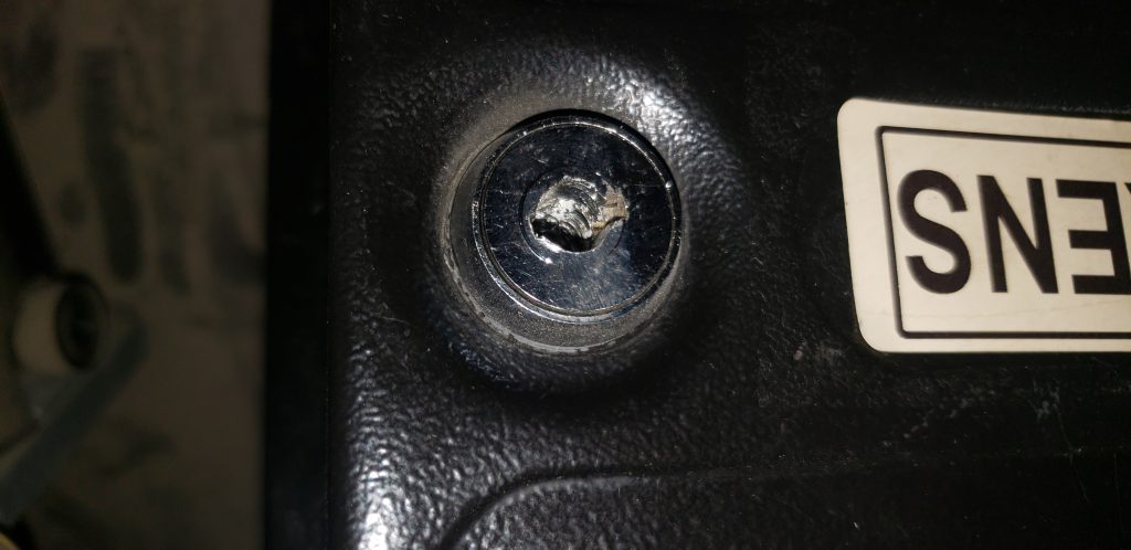
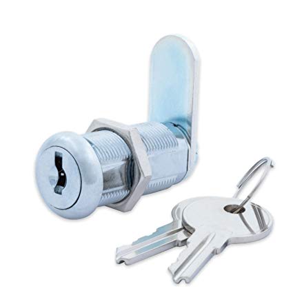
I then installed 3 new locks in each unit by removing the large screw at the back. Each cabinet need 2 7/8" locks for the coin door and 1x 1 1/8" for the rear wood door on the back. I ordered all 6 locks with the same key for ease of use.
To summarize we still have many problems left to fix.
- Both monitors are oversized horizontally and the monitor controls cannot resize the image
- One monitor is VERY dark
- The seat units are not removable (needs modification to fit into my basement)
- The wood around the seats is damaged on both units.
- The wood that covers the back is damaged on both units
- The seat sliders are very loose
- The unit is VERY Dirty... and Very hard to clean
These fit into 4 groups
- Woodwork and cleaning
- Monitor repair
- Seat repair
- Cleaning
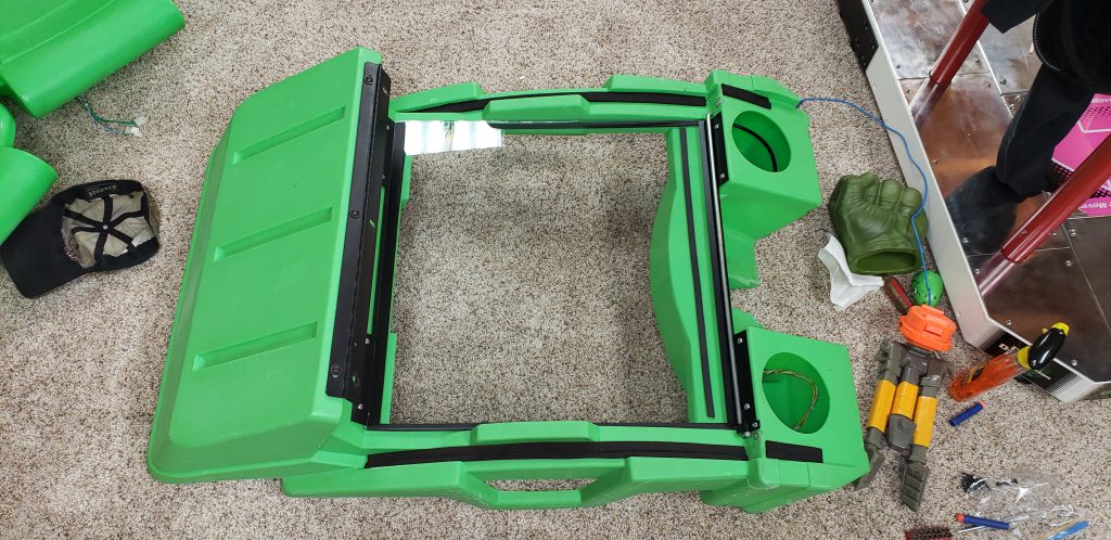
I decided to conquer monitor repair first. The monitors both need new cap kits to solve the horizontal size problem, new pincushion caps to fix the alignment problem, and a new Hot chip. One monitor needs a new flyback to fix the brightness problem. The other flyback works but it's from 1994 and had visible cracks in it, so I may as well replace it anyway.
The first step is removing the monitor. The first step is to ground out the suction cup on the back of the monitor. This suction cup can have a lethal amount of voltage on it so I use a long screwdriver and have one hand behind my back to make sure I don't die.
Both monitors are the same NeoTec NT-27E monitor made in 1997. Now that the board is removed I use a sharpie to put a black dot on the top of each and every capacitor on the board. This will help me identify which caps have been replaced and not replaced. Once all of the capacitors are replaced and the flyback has been replaced the tube can be cleaned, the circuit board can be cleaned and everything put back together. I used paper towel and distilled water to wash down the tube. Picture tubes pick up a lot of dust and dirt due to the static electricity that they create.
When put back together things didn't get better, the monitor was still super dim. New caps, new flyback changed nothing with the brightness problem. But it did fix the horizontal resizing problem. In the end, there were 2 bad resistors on the main monitor board that had gone bad. it took me 4+ hours to figure that out over several days.
Now each monitor works like it did the day it rolled out of the factory in 1997
On to the Woodwork!
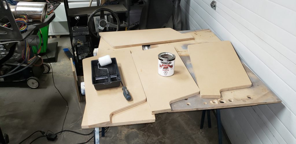
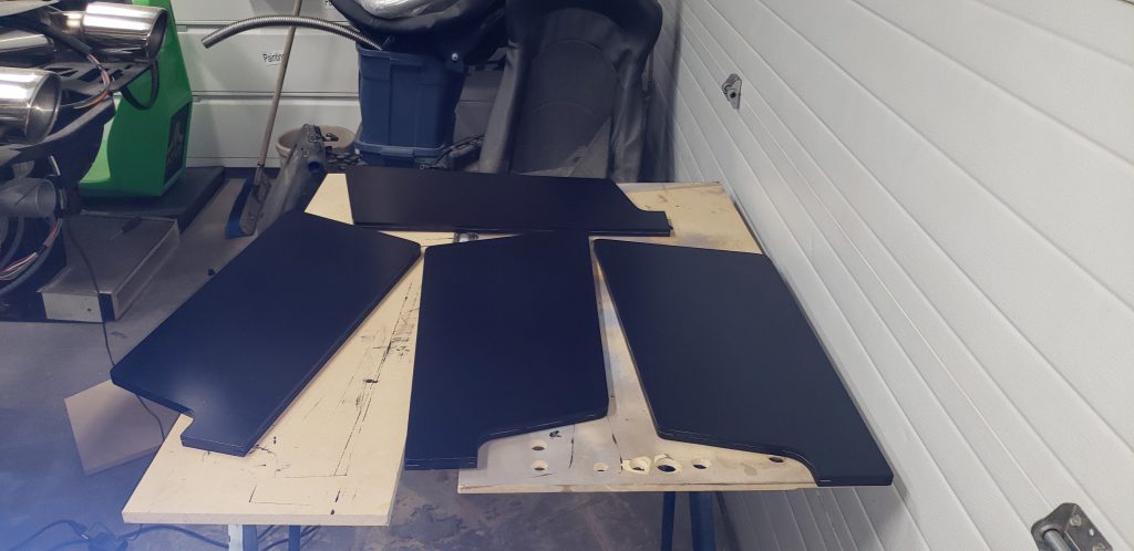
The rear door is 3/4" particle board painted black. Over the years it looks like it was dropped a few times and the main wooden bracket that holds the bottom in was removed. The easiest way to make new doors is to use the old door to trace the shape and cutouts onto a new piece of 3/4" MDF. Once complete its painted black and a new wooden bracket is added to the bottom and the new lock is moved over.
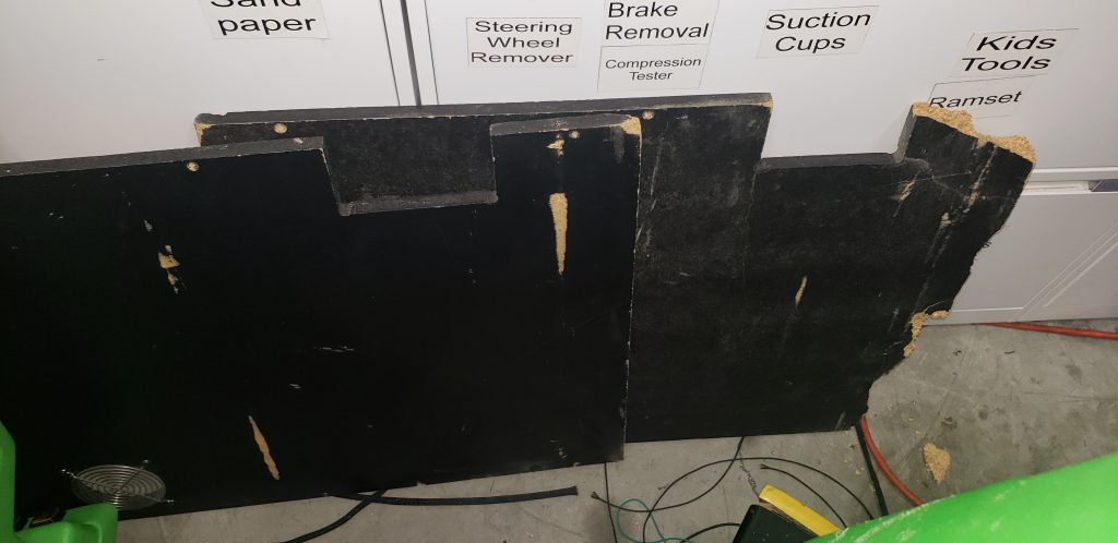
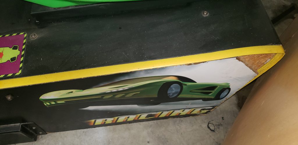
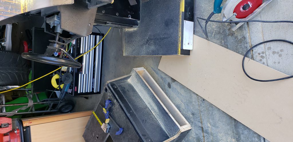
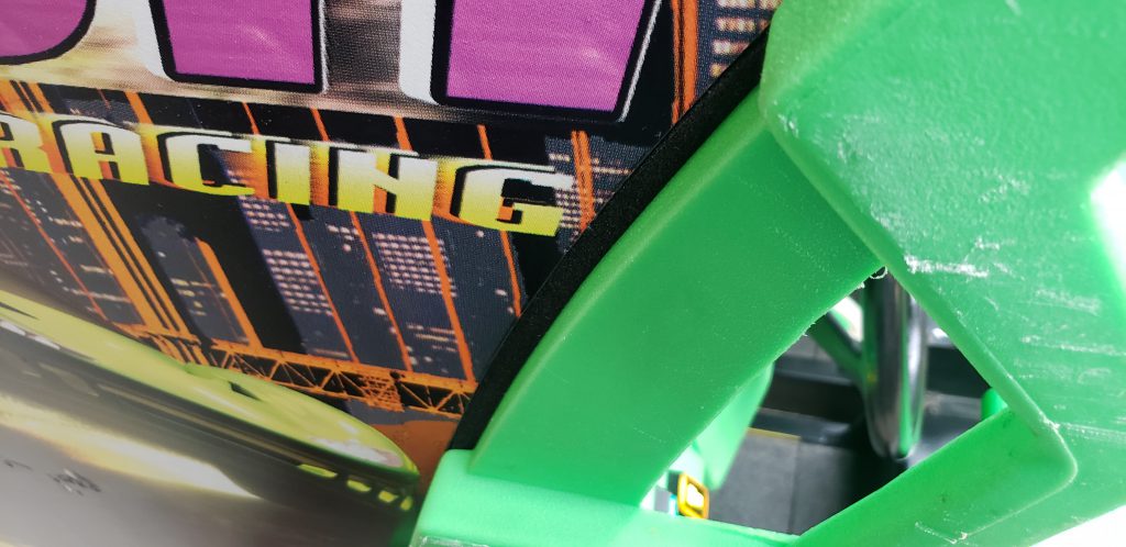
Now over to fix that wood on the sides of the seat. Removing the seat metal exposes the inside of this cabinet. From the inside, the side support can be accessed and the side removed. The removed wood can then be traced onto a new piece of 1/2" MDF. These were then painted semigloss black to match the original cabinet. Unfortunately, I have not yet found replacement stickers. I have kept the old graphics to scan at a later date so I can make a new sticker and get it printed.
Now the only problem is getting the unit into my basement. There were 2 types of cabinets made at the factory. The first style came with San Francisco rush and the second came with San Francisco rush Alcatraz edition. It would appear that my Alcatraz edition was upgraded from an original San Francisco rush and does not, in fact, come apart. This is easy to fix with a saw and some free time.
The best place to cut the unit is just in front of the rear seat. This seam will not be seen once the unit is assembled. By removing the seat access to the inside of the cabinet will allow for wood supports to be added where bolts can hold the two units together. I also purchased 4 leg levelers for each unit to add on either side of the cut so no additional stress is placed on the joint.
Now they were taken into my basement and I started to put them back together again.
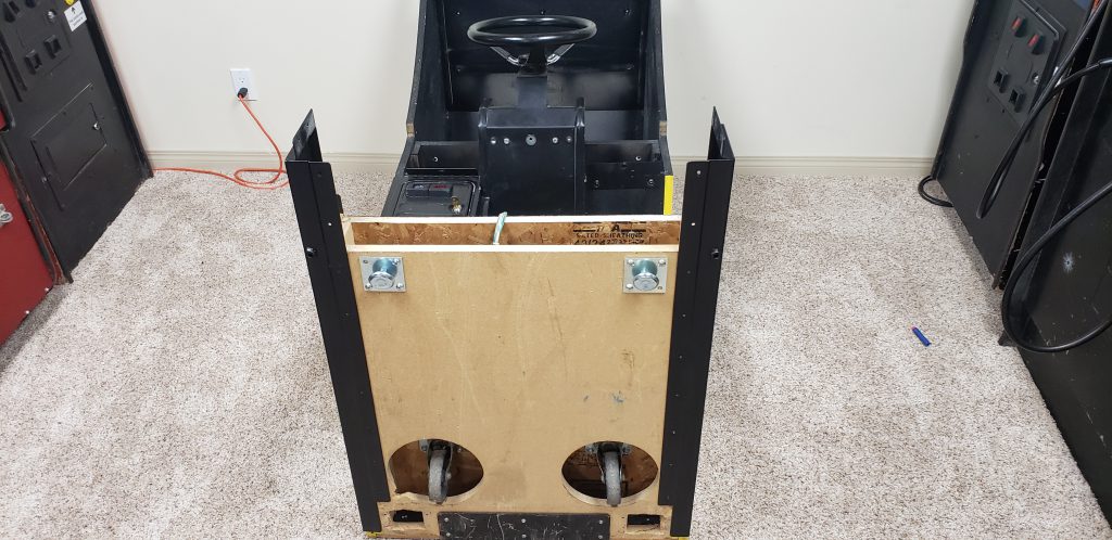
With the monitor removed I lied the unit on its back and remounted the now sanded and repainted metal brackets that came with the unit. I also added 2 leg levelers to reduce stress on the joint.
I sanded down the metal seat bases and repainted them as well and added new T molding to the seat bases. I used black T molding because its what I had... I may buy yellow to match the original factory color at a later date.
There are still a few items left to take care of
- The seat sliders are very loose
- The unit is VERY Dirty... and Very hard to clean
The seat sliders were an easy fix. I found the exact same sliders on a car parts website online. $80 for 2 brand new sets that bolted right in place of the original units. The old units were unfixable and had lost most of the ball bearings that made them slide easily.
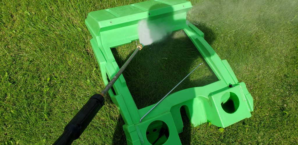
Just cleaning and reassembly to go! I took everything back apart and removed all of the electronics from every green plastic piece, this means every speaker, switch and wire.
At this point, I also removed all of the foam gaskets. these were in bad shape anyway and needed to be replaced. Once I had everything apart I took it into the back yard and pressure washed everything with a 3000 PSI pressure washer being careful not to damage the stickers that could not be replaced. I left everything out in the sun and noticed that a lot of the dirt had remained. I ended up scrubbing everything down with orange hand cleaner several times and pressure washing again. Over a few hours, I managed to get each part back to its original green shine.
Now everything started to go back together. I bought new weather stripping to replace the old gaskets. Several thicknesses were required, I told the old gasket to Home Depot and bought the closest match I could find. In the end it all worked perfectly.
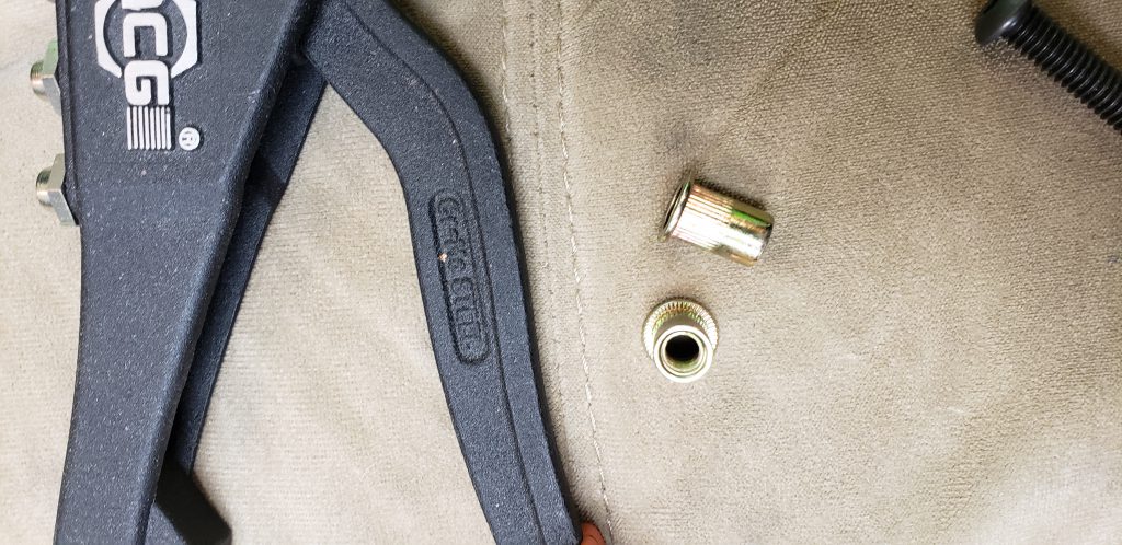
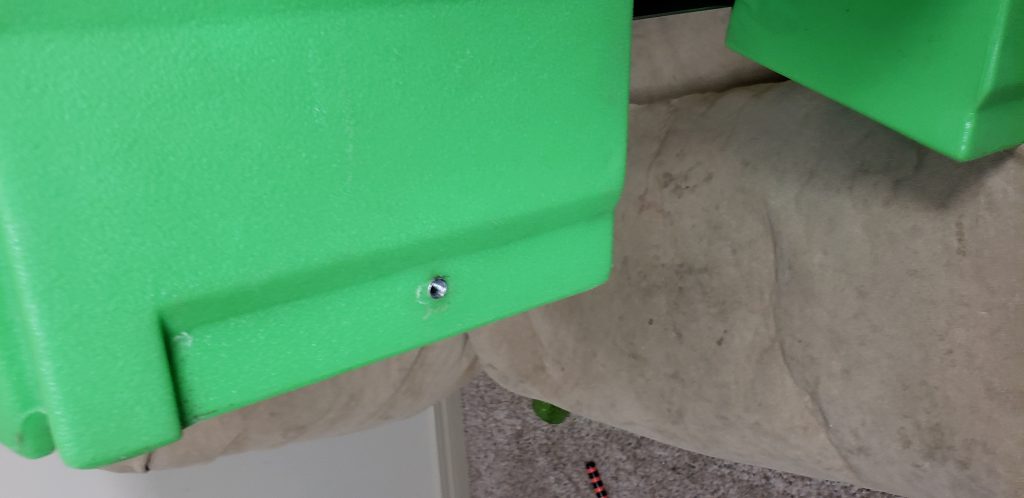
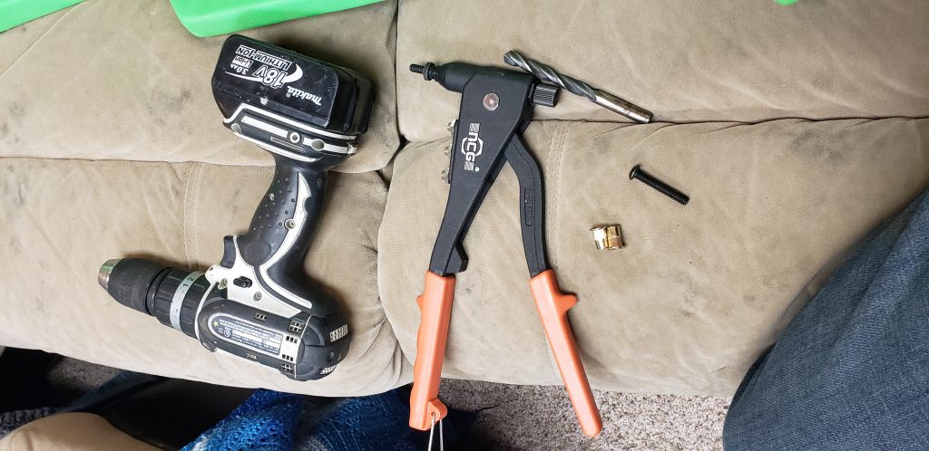
It was at this point that I noticed that the lower bolt holes on both monitor surrounds were broken, the factory retained T-nuts were broken off. To fix this I drilled out the holes slightly and installed new 1/4x20 Rivnuts that were able to take the factory bolts.
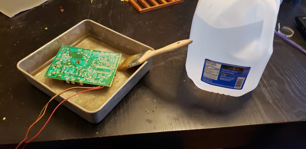
Now with the cabinet all clean I started to focus on cleaning all of the circuit boards. I placed each board in the dishwasher to get off the bulk of the dirt then rinsed each board in distilled water using a new paintbrush to make sure that all the hard water the dishwasher left behind was cleaned off. Everything was then dried with compressed air and left overnight to completely dry off.
Then everything was put back together and some small items were taken care of
- I made new monitor surrounds out of large sheets of cardboard from the dollar store, one unit didn't have one at all and the other unit was really dirty and hard to clean. I traced the dirty one out twice and cut out identical copies using a Xacto knife.
- I replaced every security bolt with new non-security bolts and new washers. Factory black.
- I used a piece of T molding to cover over the joint where the units were cut apart.
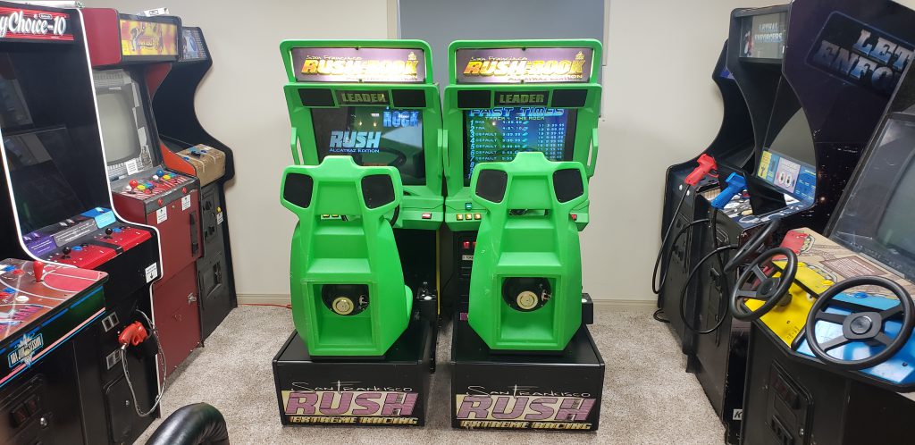
Now I have two working clean linked units. Total cost after wood/shipping/parts/etc was around $1340 CAD for the pair. Which is still a pretty good deal. Any units I have found in the past were about $900 each and needed monitor work or cabinet work or both. So I feel I still got a good deal even though the issues were a little more extensive than I had first thought.
Dead RV Camera
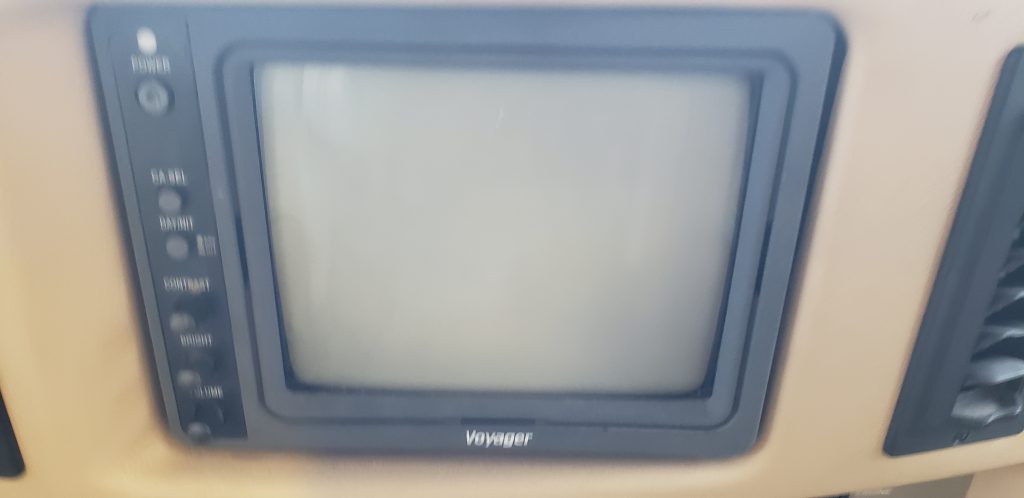
More RV problems. The passenger side camera stopped working.
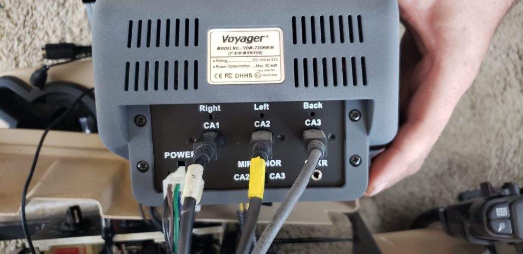
This is a photo of the back of the monitor, I tried hooking up the passenger side camera to the driver side monitor input. That showed me that the camera was in fact broken.
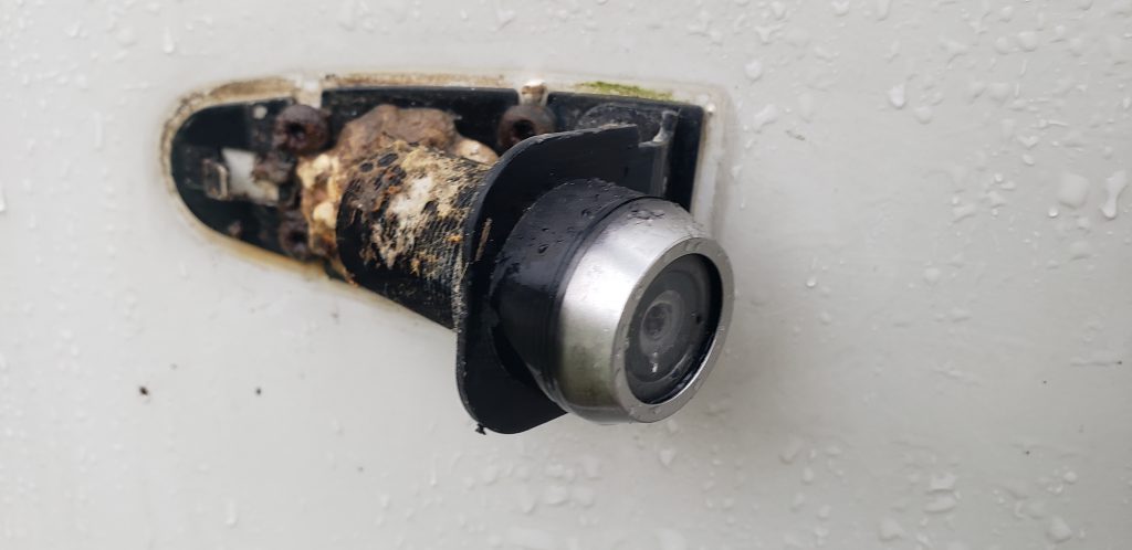
I removed the two screws that hold the cover on, Using this photo i was able to find an identical replacement on Ebay for $80. The new camera bolted back into the same bracket without any issues. I then filled the hole and screws with silicone.
Always a win when you can fix something on the RV for under $100
RV Problems
When heading home from camping last year the engine in the RV started to overheat and the check engine light popped on. I pulled over to let it cool down, no coolant was leaking, everything seemed fine. Once cooled down the RV was fine, I got up to 100Kph and it didn't overheat again. When I pulled it out after it was in winter storage I found that it would stay cool when moving 100Kph but not for stop and go traffic.
I started with the obvious, the thermostat. It can be accessed through the floor between the driver and passenger seats. Unfortunately this did nothing.
Next, I replaced the cap to the coolant reservoir.... turns out I am not that lucky.
next up was the temp sensor. The RV never boiled over or steamed... so i thought that maybe it was just lying about overheating.... replaced the sensor, no change.
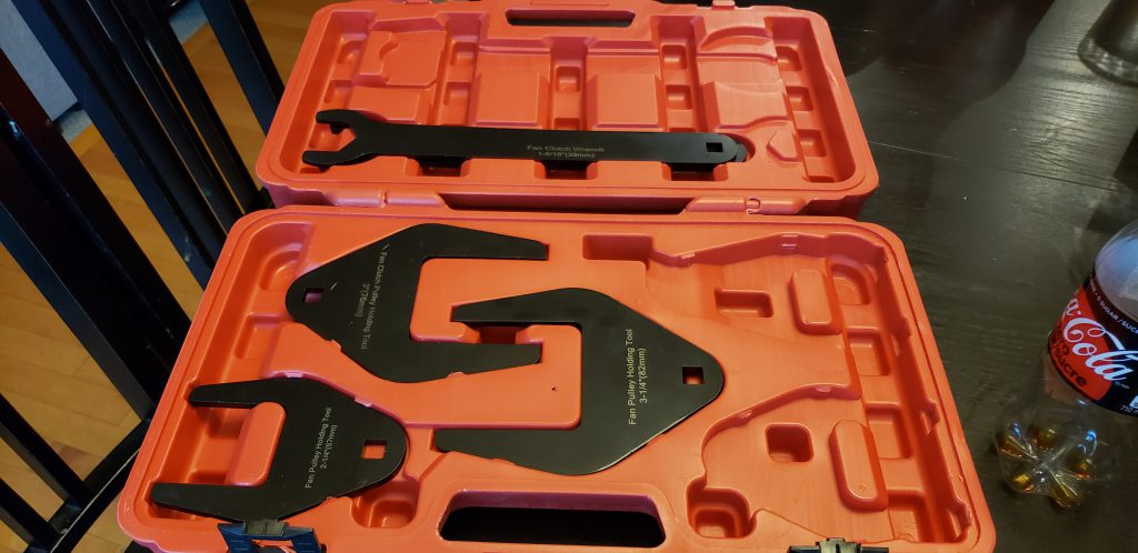
Next up was the mechanical cooling fan, for this I needed to buy some new tools, even with these tools the fan is really hard to get to. Anyway, no luck, didn't fix the problem.
So the only things left are the radiator itself or the water pump. the water pump isnt leaking but if I am going to go to all the trouble of removing the radiator I may as well replace the water pump while I am there.
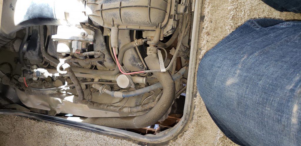
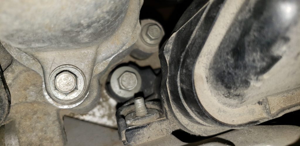
I had to remove a bunch of wire clips from the fan shroud. After that, the two bolts from the top of the shroud were removed. The shroud itself is still locked in by the fan clutch.
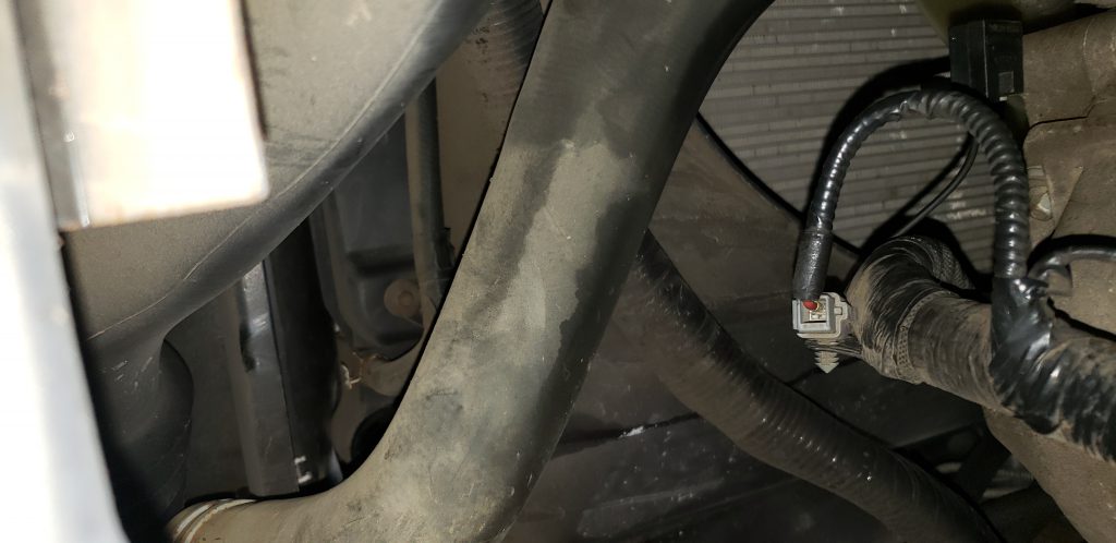
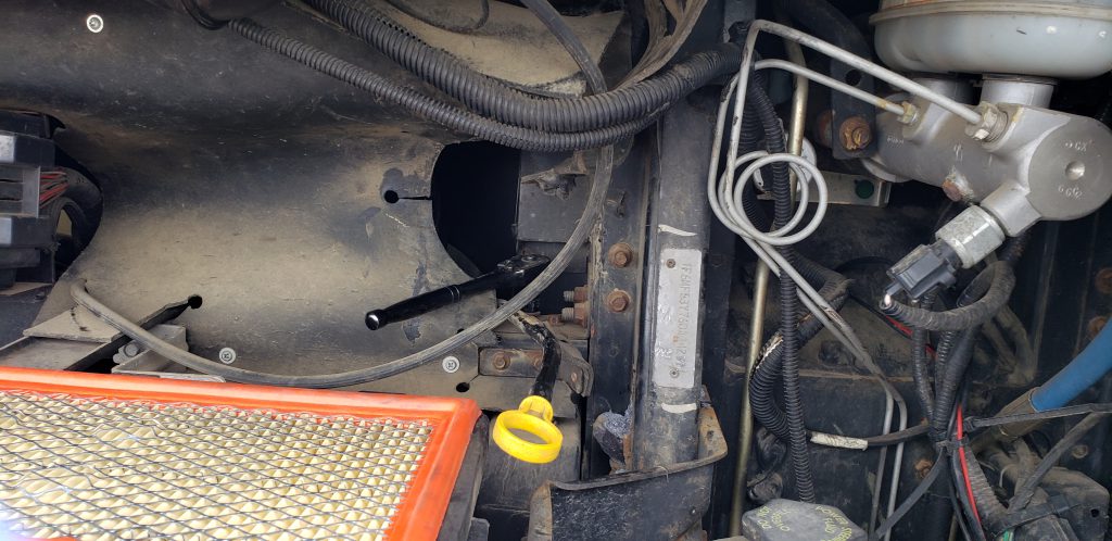
Now from the front of the RV I dug down to the bolts that hold the top of the radiator down The Airbox had to be removed and some rubber shrouding.
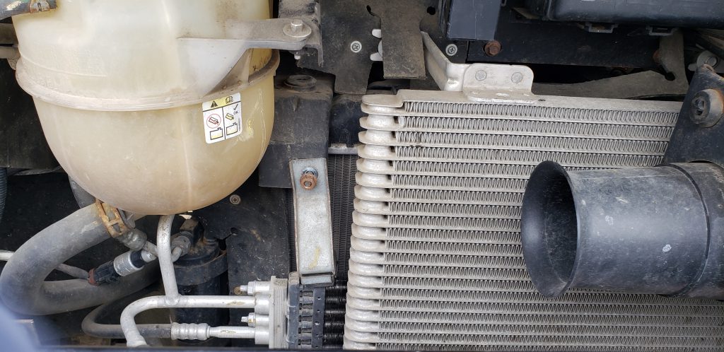
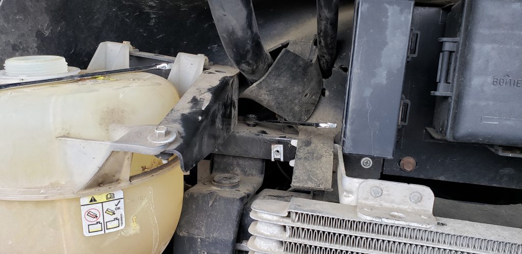
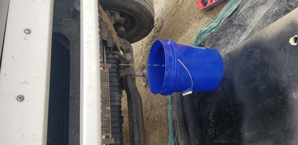
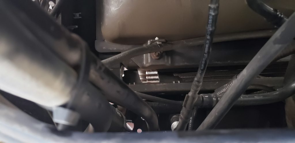
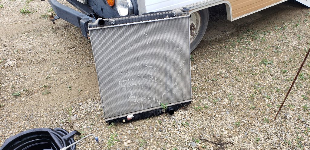
now I could disconnect the trans lines from the radiator and the upper and lower rad hoses. Now it's possible to remove the mechanical fan so it sits inside the fan shroud. Then remove the shroud with the fan inside it. Then the radiator can slide up an inch or two releasing the bottom pins. Then the base can be slid back toward the engine and down to the ground. The RV had to be jacked up 2 feet to make room to fit the radiator out the bottom.
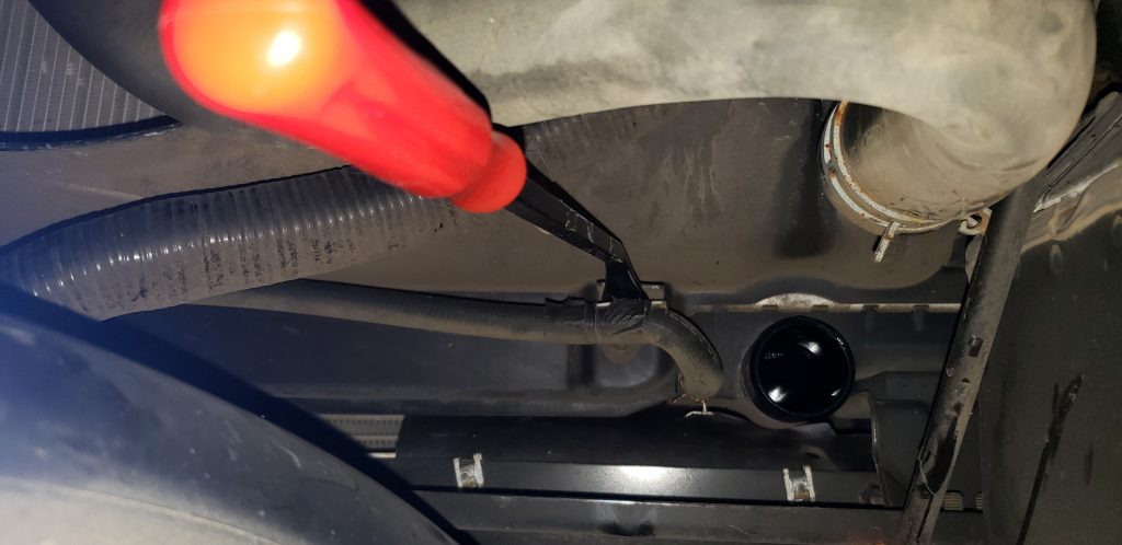
Now I could get to the front of the engine by putting my body where the radiator used to be. I removed the belt and removed the pully from the front of the water pump with a puller. This gives access to the bolts that remove the water pump.
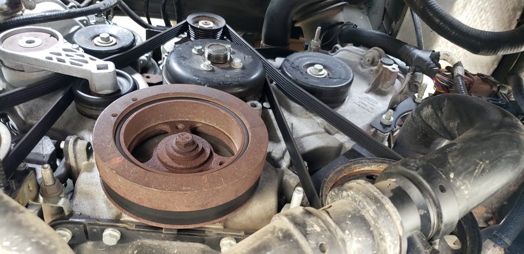
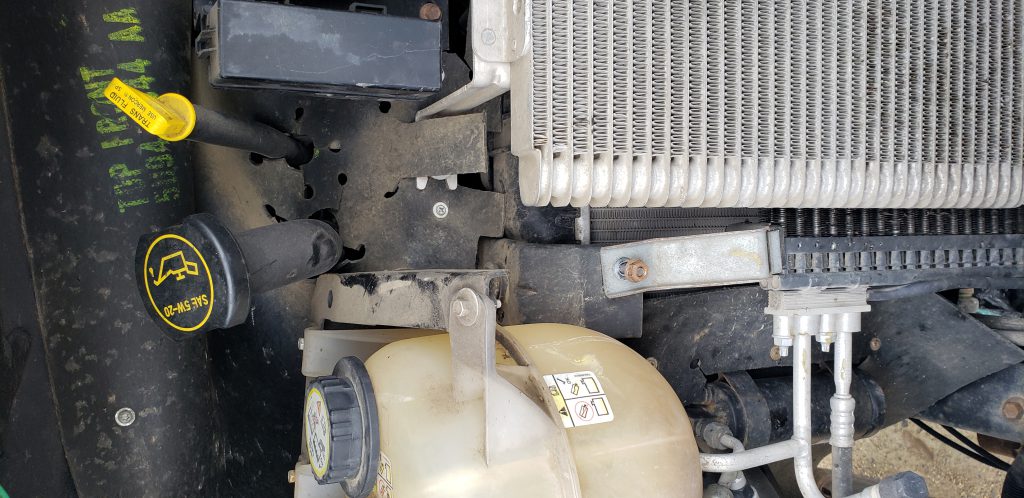
Then the new pump went in using a new O-Ring. Belt was reinstalled, new radiator installed, fan shroud reinstalled with fan loose inside. Fan then bolted back up and all of the lines were reconnected.
Camping Projector Mount
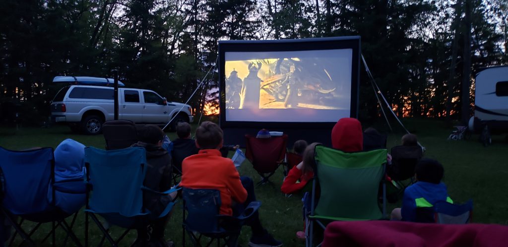
A few years ago I purchased an inflatable projection screen that is made out the same material Zodiac boats are made from. We have used this a number of times while camping but the projector is always hard to setup. It requires pulling over a picnic table which obscures the view or piling up logs to try to get the projector in the proper place. The company i work for makes short throw projectors so an experiment needed to take place.
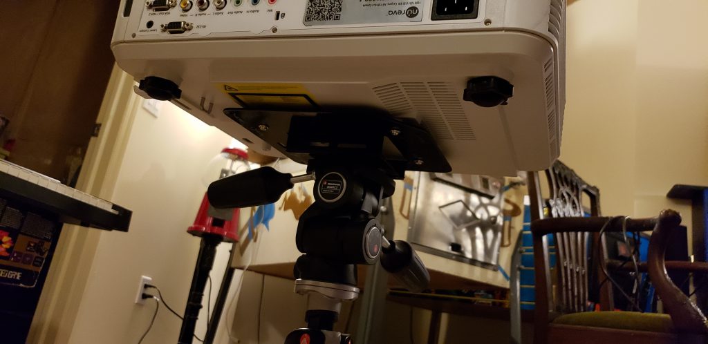
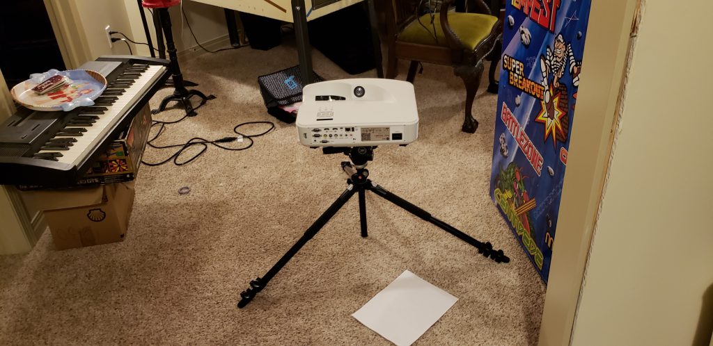
I took our factory projector plate and welded a bottom plate to it. I then tapped the plate with 1/4x20 hole to receive the tripod mount.
I would say that this was both a success and a failure. The tripod mount was a win. However short throw projectors should not be used for outdoor screens. The screen moves in the wind and small changes to the screen make large changes in the picture size and shape. So when the wind gusts, the picture moves drastically. Once i got home i created a new plate for my NEC long throw projector. This will work better moving forward.
Windshield
So I called FF to see if i could get a new windshield to replace the one that broke when a gust of wind separated it from the body and blew it across my yard....
Each windshield costs $250 USD... Reasonable enough. I asked FF to quote me the price for 2 shipped to my house (in Canada)
2 windshields international Priority shipped to my door: $4,975.36 CAD
2 windshields international Economy shipped to my door: $4,097.78 CAD
2 windshields shipped to Montana (so i would have to drive for 6 hours to go get them) $1,601.87 CAD, + storage fee at a border crossing receiver + duty at the border ($34 or so)
so about $800 + duty a windshield if I order 2. (still the most expensive piece of glass i will have ever bought in my life.)
So... anyone in Alberta want an extra windshield, this gets cheaper if i go and pick up a few, then we can split the shipping costs. The 6 hour drive will be on me.