TCPIP Washer
 A few years back my wife and I purchased a Whirlpool Cabrio washer. I remember at the time we were looking there was a top of the line model that worked closely with home automation systems to start cycles and notify via the automation system when cycles are completed.
That kind of stuck with me as something I had to have, not sure why as it seems like something everyone could do without, but I think it could be fun.
To start on this quest I had to understand how the washer works in order to figure out how to modify the system to add a network interface.
The first problem to overcome was the fact that my wife didn't want me to take the machine apart in fear that I may break it. This was an easy hurdle to overcome as my wife has a standing appointment away from home every Monday night. So this means I could work in short 2-3 hour shifts on Monday nights as long as the machine was reassembled before she got home.
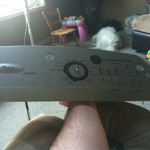
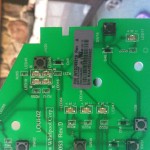
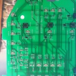
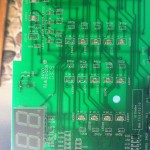
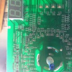
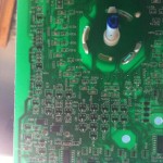
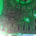
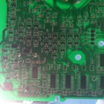
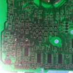
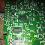
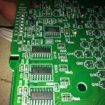
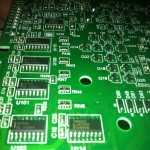
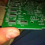
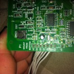
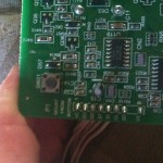
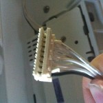
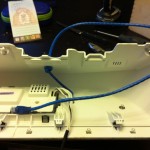
Here are some photos I took of the top panel guts during covert mission day one.
The chips on the board are a series of bit shift chips. Here are the chip details.
If you have never seen a bit shift operator it can be explained fairly simply in 4 steps:
1 Set the data pin to high or low for the first output pin on the shift register.
2 Pulse the clock to ‘shift’ the data into the register.
3 Continue setting the data and pulsing the clock until you have set the required state for all output pins.
4 Pulse the latch pin to activate the output sequence.
Now if you look through those images above you will see the interface is labeled on the board.
1) VCC 5Volt
2) Data out (reading buttons and encoder wheel)
3) GND
4) STROBE (latch)
5) Data IN (Shift Register that control LED's)
6) Clock
7) Spk_DRV
8) UNUSED (NO WIRE)
9) V_SPK
First thing you will notice is it has both input and output but only one Strobe and Clock set of pins. If you look further at the board you will see that the input shift registers and the output shift registers are attached to the same Clock and Strobe wires. So every time we strobe in new data we read out data, and every time we Clock in a full set of data we also Clock out the output.
The logic seems to work like this
- Panel gets 5 volts on pins 1 and 3 when the washer is plugged in (doesn't have to be on)
- Washer board (in base) sends goes high or low to shift in the current settings data
- Washer panel is filled with shift registers which record current button state
- Strobe pin goes high then low, steps 2/3 fire again for next input output, strobe pin goes high then low, and it repeats until all data is latched in and out.
- Clock pin goes high then low to latch the data in.
So my plan to get a TCPIP control is pretty simple. I plan to get in the middle of this communication. From this location I can fake button input and read the LED output registers.
Using an Arduino and two interrupts I can watch the data be strobed and clocked in while saving the data to a variable. I can then replay that strobed data out another couple of pins on the Arduino to update the panel. The Arduino can even grab parasitic power from the bus.
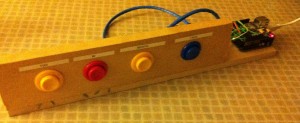
This was the first test setup to test out the code I had written. Each button has a simple pull down resistor and maps to the Arduino pins that I will be using for Clock/Latch, Data In and Data Out. I could then use this to ensure my code could save into the variables as expected.
WashCodeV1.ino (Not complete code, just test to print bit shift to serial)
Once this phase was completed it was time to hook it up to the washer and see what happens. I soldered a cat 5 cable into the existing panel contacts at first so I could monitor the data being shifted in and out. I initially had trouble with the circuit until I optically isolated the 4 data pins on the washer from the Arduino.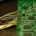
I tailored a sample piece of code to simply save the clocked and latched information into memory with a small web server app to show what data was in the registers at any one time. Once hooked up I was able to read the input and trigger button input from the Arduino but was flying a little blind on which shifted bit lights up which LED or triggers which button input.
There were two choices to understand this data,
One: go through each trace on the board (LED And Switch) and map them to pins on the bit shift registers. Then follow the traces to the registers to see what order they were shifted into and out of.
 Two: Trial and error, finish the code to output the current shifted array back to the factory display panel, then mark down what lights are lit and compare them to the 1/0's from the shift registers. Change one LED using an input button and see what data has changed. Then repeat that a few dozen times.
I decided to with option two, everyone loves a mystery, and lets face it option 1 is boring as hell!
This is where I sit today..... Patiently awaiting the next Monday of discovery.
