More car progress
Trans is now attached to the engine. (two of us just lifted it up and bolted it in).
Now there are some new problems to solve.
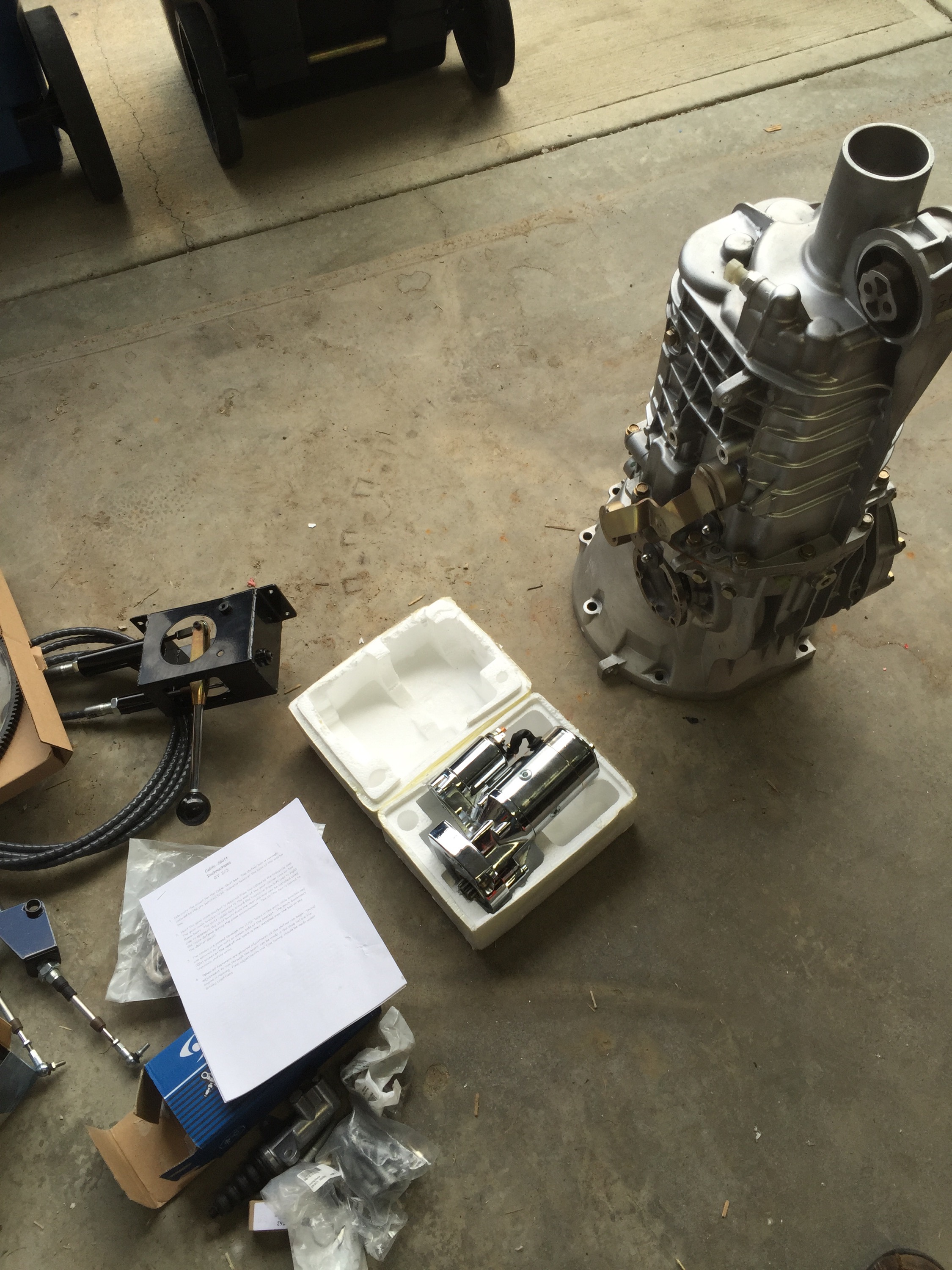
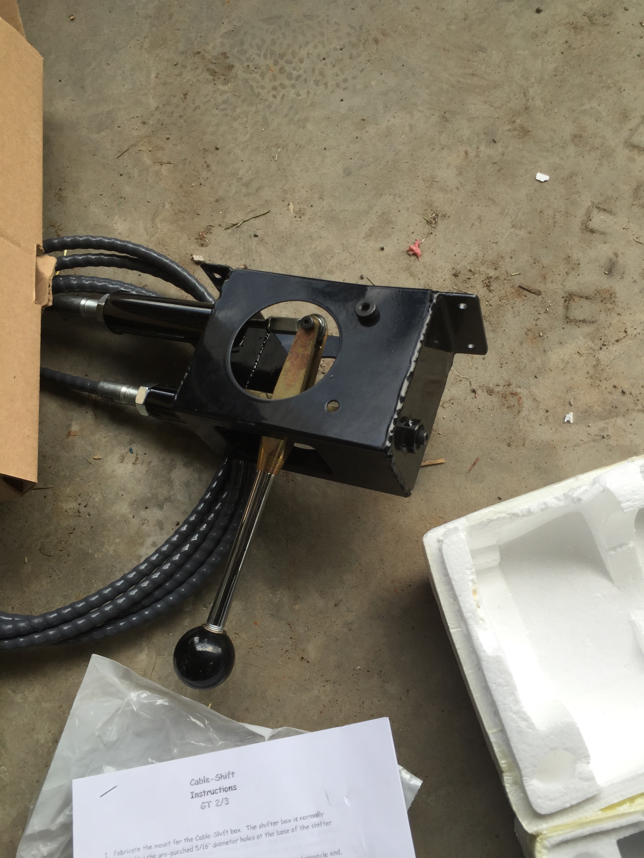
1) the shift linkages will need a custom mount created and welded together. The factory trans holes wont work.
2) Back to the problem I was having with rear tire alignment. The problem has to be one of two things. 1, the tie rod end is to short, 2, the tie rod itself is to short. Maybe they are not factory. Can someone check there set and let me know which one is right. The rear tie rod is 4.75 inches long, the front tie rods are 9" long. by my calculations the right length would be around 7.25". The tie rod itself is 12.5 inches long, measured from the plate it bolts into to the threads that the tie rod screws into. (see pictures).
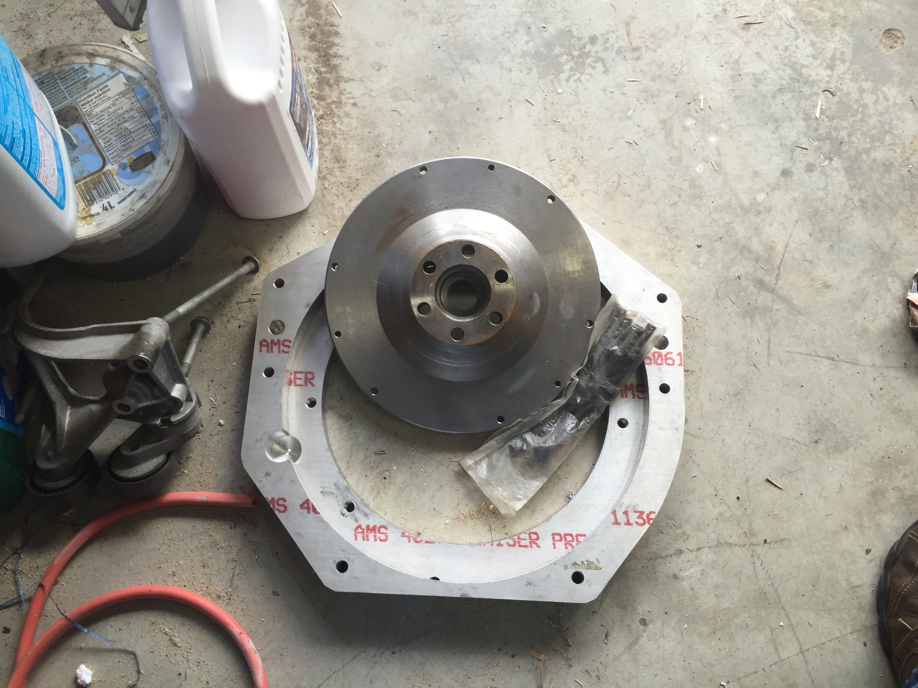
3) (didn't take any pictures) The trans doesn't fit into the GTM rear trans mount. The trans mount is 1/2 or so thicker then the G50 mount that the GTM comes with. I will have to cut off the factory trans mount tabs and weld them back on a little wider.
I am going to have to make more time moving forward.
Volunteered to help build a garage... weekends lost.
Volunteered to help remove a 25 Kva generator from a multi million dollar home because the owner let me keep it.
After talking with the guy in that home he mentioned that he had a quad trail on his property that he wanted to use but it was now overgrown with trees. So he bought me a new chainsaw as payment to clear out the trail that covered 150 acres of land. I underestimated the time required for this, but it was a TON of fun. (and I got a free chainsaw :-))
I received my first order of Vspeedworks parts and they are really nice ( I needed the shifter mounts, figured I should order a few more parts while I was at it)
I found this diagram that shows how to mount the slave, etc.
Heres what It looked like complete.
This is how I plan to get someone to help me lift it up.
This weekend I am heading out camping (last time this year as the snow is already starting to fall here).... I hope to invest more time in the weeks to come.
Productive Weekend.
So day one started with me going to work because something went wrong and i was on call so i didnt get quite as far as i wanted.
Day One
- Garage Cleaned up
- All Bolts tightened to spec.
- Steering wheel mounted
- Pushed the car down the driveway, spun around and placed onto the lift with the back facing out. (ready for the engine)
- Picked up the engine hoist from a friend.
- Engine s
- ensors removed and replaced with FF units as per instructions.
Day two
- alternator bolted on
- Air-cond pump bolted on
- Tensioner setup
- Serpentine belts put on
- Removed the engine from its stand and placed onto crane
- bolted the engine mounts back on
- Put the block heater back in (got in the way of the stand)
- covered the inside of the engine bay with blankets
- tried to fit the engine in.
- realized that the manual was right and the thermostat does have to come off to fit.
- removed thermostat, tried again
- bolted engine in, held back end up with ratchet strap
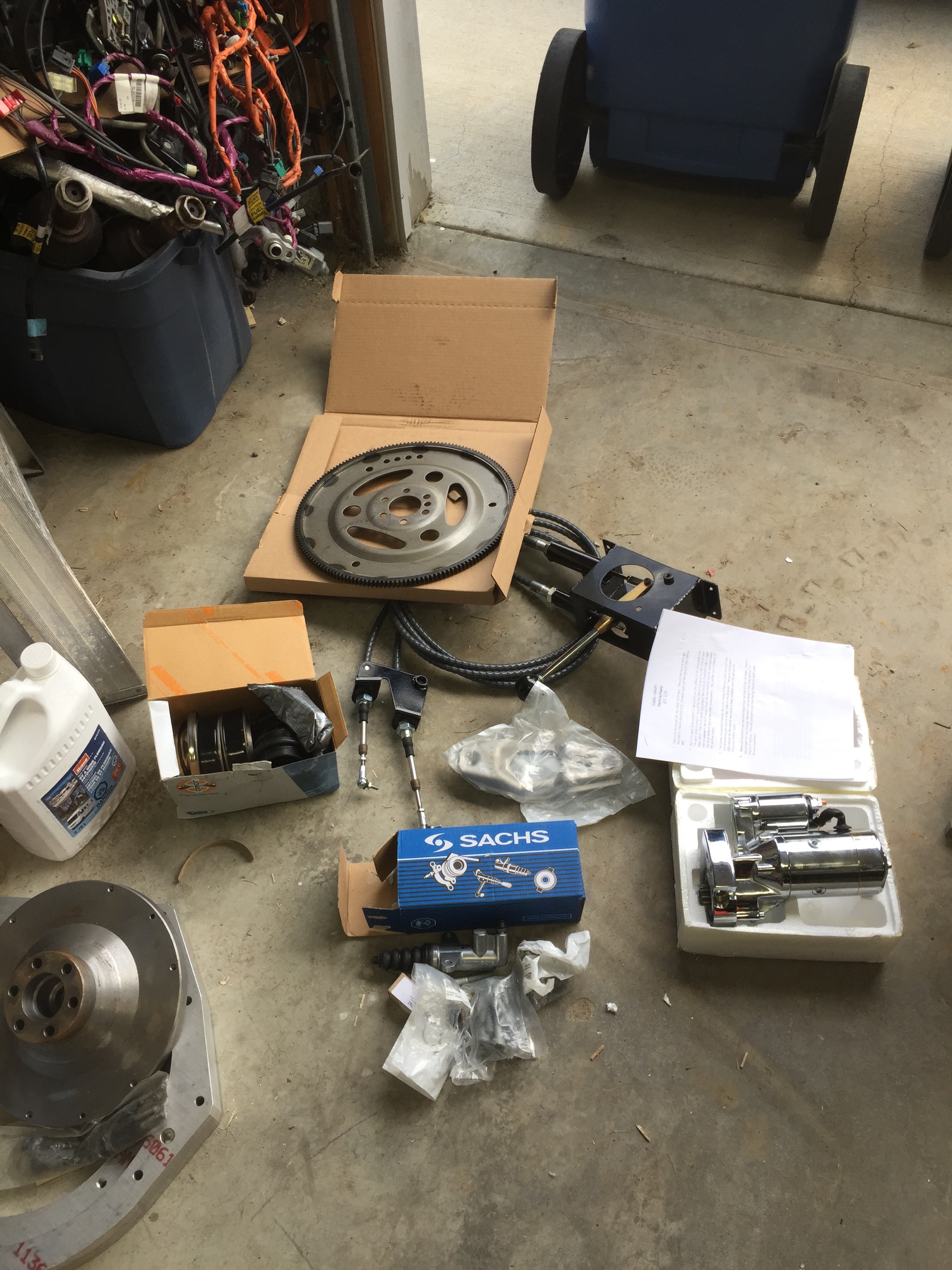
- bolted the starter ring and flywheel on.
- put the bearing onto the flywheel
- put the trans/engine adapter plate on, (realized i only had one bolt that would work)
- Went to the store to buy more bolts.
- bolted the adapter on.
- bolted the clutch on
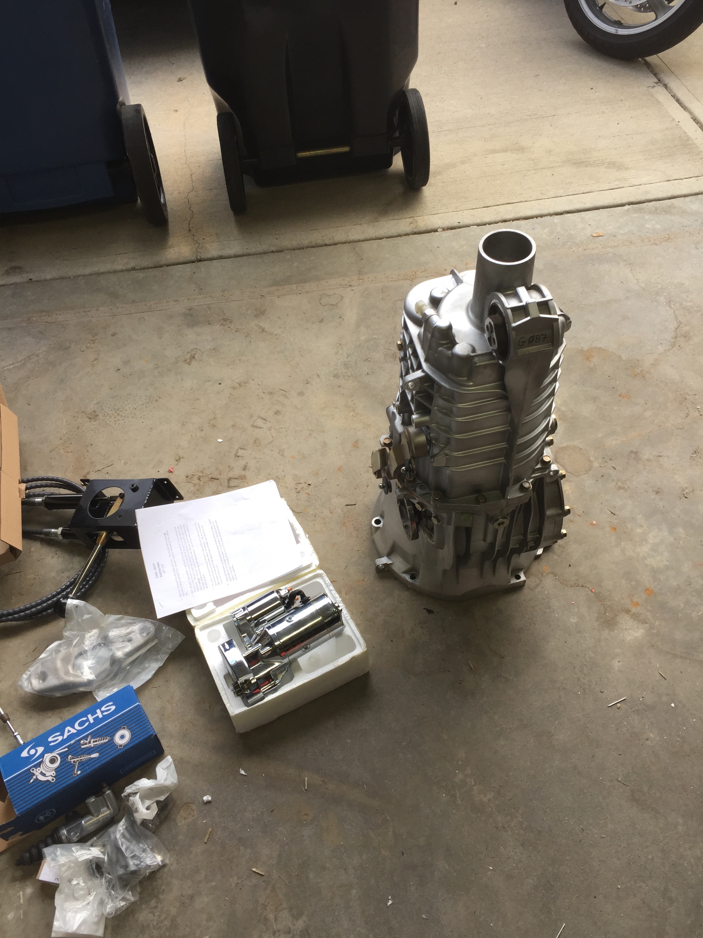
- installed the clutch slave onto the trans
- installed the pilot bearing, etc. onto the trans.
- identified and purchased the bolts required to mount the trans....
- .... ran out of time.
My wife is out tomorrow evening so i should have enough time to mount the trans to the engine and the rear support.
Shocks are now assembled and the front 2 are now mounted. I only had about 45 minutes yesterday so i couldn't get it all 4 installed.
I also installed the steering rack.
These bolts still need to be torqued to spec but all 4 suspension assemblies are now mounted.
This is another problem that I cant figure out. The manual is very clear that the Rivnut has to be mounted from the top to mount the peddle assembly. If you do this you cant mount the pedal assembly anymore. It would make much more sense to mount from the bottom up. It would also allow it to be removed easy once the dash is installed. If your reading this any you remember how you handled this please let me know.
So i was able to spend a solid 8-10 hours on the car today, Some of those hours were spend running around town for parts... a great progress day regardless
Started by riveting and siliconing the aluminum around the suspension parts
Took a brake from that for a while and tried to fit the shock mount to the lower A arm, it hit the side of the A-arm and wouldn't mount all the way in. I used a cutoff wheel to take off 1/16th or so of an inch... I had to repeat this for the other side as well.
When I was in the USA picking up the kit I grabbed some Vanilla Coke... this stuff is amazingly good, why don't they sell this in Canada.
These are the spacers that attach to the bolt that holds the strut. The spacers are not large enough to fit over the bolt, I will need to drill the spacers out a little larger, is this normal?
Continued...
Took a couple days to get my life back in order, went for an interview, have another next week. While sitting at home for a year and getting paid sounds amazing it my be increasingly hard to get a job with that long of a gap in my resume. I still haven't decided but I may go back to work if an opportunity presents itself.
Back to the car....
I received the LCD screen that i would like to use for the dash, I still have to test it out and find an LVDS adapter to drive it via HDMI. I plan to take the screen out of this plastic housing and build it into the gauge cluster. I still have to make sure
Concrete company came on Tuesday, they helped me carry the GTM frame out to the lawn and they started drilling 17 3" holes in the floor in a grid pattern. Once drilled we could see that the problem was even worse toward the back of the garage where there was almost a solid 12" of air under the 2" slab. They then used a high pressure pump to push concrete into the holes. You can even start to see water and concrete start to squish up through the cracks in the floor. The whole operation took 2 hours and cost $1800.
All of the parts are now back from the powder coaters and ready to be riveted to the car. They look amazing. I ended up going with the semi-gloss black, total cost ended up being $600
Moved everything today across town into an empty garage that someone let me use. Threw the scoop on top to see how it would look. All of the boxes for the interior, body, glass, seats, etc fit inside the car.
On the drive across town i watched a few cars start to pass me, hit the brakes look at the trailer a few times, linger there for a few minutes then take off...... as we got off the fast roads and back into a community my 6 year old in the back seat of the truck asked me "why is everyone staring at the trailer".... cant imagine how much attention this car draws when its finished.
Reinstalled the lift today (its been close to 28 days since i poured the new concrete). I had a little fun lifting the frame up and down a few times, for now its not directly on the center of balance (i couldn't move the frame alone). I rented a hammer drill, it didn't go as well as planned and ended up taking 4 hours to drill all the holes.... I broke 4 crappy drill bits, getting them back out of the holes is not easy.... I should have bought better bits.
And in the afternoon the first portion of my Canadian GTM kit came in the mail... $270 in customs fees.... ouch...
Box has
- The brake lines (2 sizes)
- 4 shocks, 4 springs, 4 spring hats, 4 adjustment collar
- Painless harness
- Slave cylinders
- Gas Caps
- Gas filler hoses
Still missing the steering rack and some of the shock parts.